


System Options:
EasyLift
C O N F I D E N T I A L – FEI Limited Rights Data
7-19
EasyLift Basic Procedures
TEM Sample Preparation
Bulk Milling
In bulk milling, enough material is removed to guarantee the membrane will be free during lift out. This procedure is
identical for all systems and port assignments.
1.
Place the feature of interest to the eucentric position.
2.
Deposit 20 to 25
µm
in X direction, 2
µm
in Y direction carbon or tungsten protective layer. Make sure the
deposited protection layer is thick enough, usually it should be between 2 to 3
µm
thick. Use the electron beam
to deposit before the ion beam deposition if necessary.
3.
Place two cross-section patterns, 5
µm
apart, with sizes of
roughly 35 × 11 × 6
µm
. Rotate the upper pattern by 180° so
that the deepest part of the cross section faces the feature.
Note
In practice, the Y-dimension depends on the Z-depth. To make
sure the bottom can be easily cut-free from the bulk material,
the Y-dimension should be around 2× of Z-depth.
4.
Using the 20 nA beam current, mill the two cross sections
in Serial mode. Total milling time is about 25 minutes for
these cross sections.
5.
Using the 5 nA beam current and cleaning cross section
patterns, tilt the stage to 56° and 48° respectively to mill
the sample from front and back side until the thickness is
around 2
µm
.
6.
Once the bulk mill is finished, the sample can be partially cut free. Switch to the 5 nA beam current and scan-
rotate the image by 180°.
7.
Tilt the stage to 7°.
8.
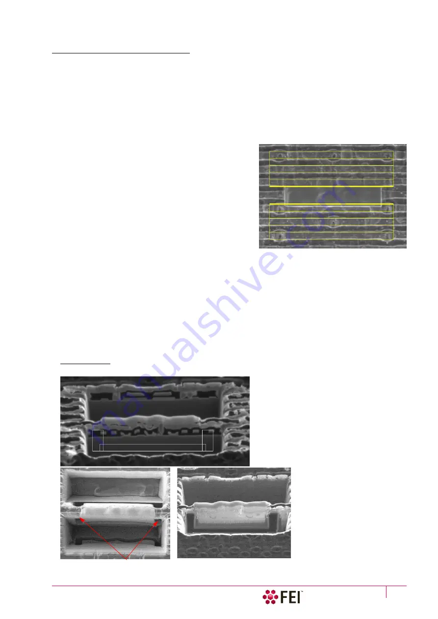
Create rectangle patterns on the membrane as shown in the following figure. Set the pattern depth to the
approximate thickness of the membrane at its thickest point – typically 5
µm
. Select the
“Si New”
application file
and mill in Parallel mode.
9.
Mill until it is clear that the milling went all the way through the sample. Use electron beam and ion beam frame
grabs to monitor milling progress. When the sample has been cut through, you will see cut marks in the rear
trench in the electron beam image, as illustrated in the following figure.
Note
It is very useful to use iSPI mode (intermittent Simultaneous Patterning and Imaging) to monitor the cutting processes.
FIGURE 7-6
Patterns for Initial Cutout (Scan Rotated) and Initial Cutout Views
Electron beam view (Cut marks)
Ion beam view
Содержание Scios 2
Страница 1: ...User Operation Manual Edition 1 Mar 2017 ...
Страница 84: ...Software Control Entering Commands in Summary C O N F I D E N T I A L FEI Limited Rights Data 3 58 ...
Страница 97: ...Alignments E Column Supervisor Alignments C O N F I D E N T I A L FEI Limited Rights Data 4 13 Focus Centering ...
Страница 102: ...Alignments I Column Alignments C O N F I D E N T I A L FEI Limited Rights Data 4 18 I Column Alignments ...
Страница 103: ...Alignments I Column Alignments C O N F I D E N T I A L FEI Limited Rights Data 4 19 ...
Страница 110: ...Alignments 254 GIS Alignment option C O N F I D E N T I A L FEI Limited Rights Data 4 26 ...
Страница 170: ...Operating Procedures Patterning C O N F I D E N T I A L FEI Limited Rights Data 5 60 ...
Страница 178: ...Maintenance Refilling Water Bottle C O N F I D E N T I A L FEI Limited Rights Data 6 8 ...


