System Options:
Optional Detectors
C O N F I D E N T I A L – FEI Limited Rights Data
7-5
Optional Detectors
The Scios microscope system is possible to extend with some detectors, depending on user needs.
Retractable Detectors Control
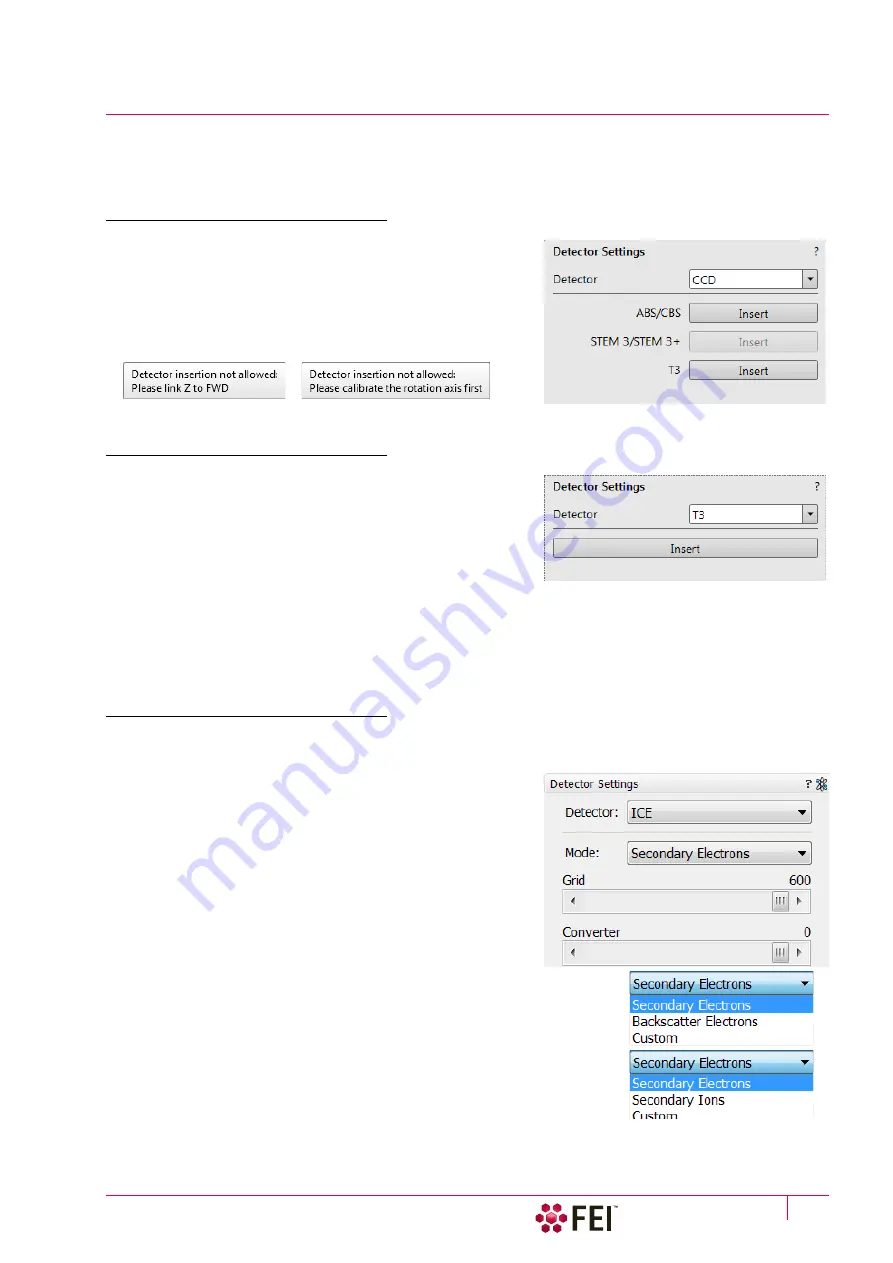
When any retractable optional detector is installed on the
system, the appropriate
Insert
/
Retract
button is added to the
Detector Settings
module /
Detector CCD
to enable the equipment
control while observing the optical imaging display. The same
button is present in the appropriate detector module also.
To insert any retractable detector, confirmation dialog appears.
When insertion is not possible, tooltip gives a reason why.
Trinity Detector T3
Electrons generated by a primary beam can be collected by the
in-column Trinity detector T3 which is located inside the column,
just below the aperture strip. It is useful in the OptiPlan and
OptiTilt column Use Cases.
It is ideal for use together with the Beam Deceleration mode (BD)
and Use case Standard and with/without BD in Use case
OptiPlan, when standard off axis secondary electron (SE)
detectors fail.
In BD mode with stage bias above 2.5 kV the detector detects SE, without BD the detector collects BSE signal.
Optimum WD should be from 3.5 to 7 mm to achieve maximum detection efficiency. Due to geometrical
restriction higher probe currents and HV over 4 kV should be used.
Ion Conversion and Electron detector (ICE)
The ICE is a charged particle detector mounted near the end of the ion column. It collects secondary ions (SI) or
electrons (SE, BSE) to form an imaging signal.
The electron beam or ion beam imaging (which is distinguished
by the beam icon in the module header) have different
Mode
s.
Electron / Ion beam modes:
•
Secondary Electrons
(SE) /
Secondary Electrons
(SE)
•
Backscatter Electrons
(BSE) /
Secondary Ions
(SI)
•
Custom
/
Custom
•
Deceleration Mode
item is available only when the BD is On.
ICE Detector Settings
When changing any of the adjuster, the
Custom
mode is activated
for any beam, enabling to change values.
•
Grid
adjuster – positive voltage for SE imaging, negative
voltage for BSE and SI imaging
•
Converter
adjuster – 0 for SE and BSE imaging, negative for SI
imaging
Note
Changing the beam current causes automatic adjustment of the
detector contrast.
Содержание Scios 2
Страница 1: ...User Operation Manual Edition 1 Mar 2017 ...
Страница 84: ...Software Control Entering Commands in Summary C O N F I D E N T I A L FEI Limited Rights Data 3 58 ...
Страница 97: ...Alignments E Column Supervisor Alignments C O N F I D E N T I A L FEI Limited Rights Data 4 13 Focus Centering ...
Страница 102: ...Alignments I Column Alignments C O N F I D E N T I A L FEI Limited Rights Data 4 18 I Column Alignments ...
Страница 103: ...Alignments I Column Alignments C O N F I D E N T I A L FEI Limited Rights Data 4 19 ...
Страница 110: ...Alignments 254 GIS Alignment option C O N F I D E N T I A L FEI Limited Rights Data 4 26 ...
Страница 170: ...Operating Procedures Patterning C O N F I D E N T I A L FEI Limited Rights Data 5 60 ...
Страница 178: ...Maintenance Refilling Water Bottle C O N F I D E N T I A L FEI Limited Rights Data 6 8 ...


