Installation
Proline t-mass 65 PROFIBUS DP
20
Installing
The mounting location is determined by the installation requirements for an insertion type sensor.
Pay particular attention to mounting orientation and inlet and outlet length. See this chapter for
details.
#
Warning!
Stop the process gas flow and de-pressurize the process line. Purge the line with an inert gas to
remove any hazardous or toxic gases. Allow the installation to cool to a safe temperature. Check
and verify that this is so before handling any metal parts. Ensure that the process cannot be re-
started during the installation procedure.
1.
A cut-out of 31.0 mm ±0.5 mm (1.22" ±0.019") is required for the process fitting. Mark the
pipe accordingly and cut the hole with a suitable tool.
2.
Finish the edges of the hole to ensure that all burrs are removed and that the required tolerance
is met. Remove any particles that may have fallen into the pipe.
3.
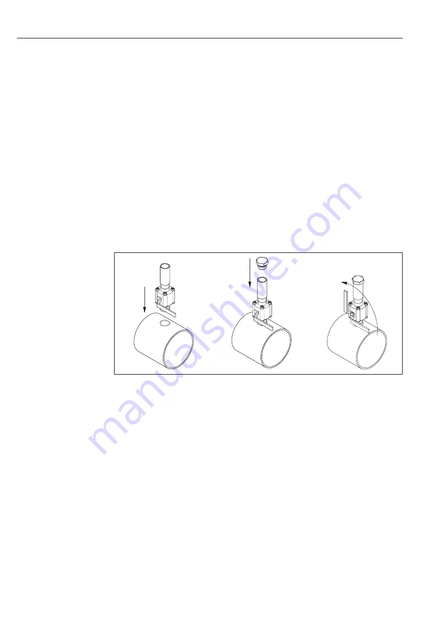
Insert the process fitting into the pipe (a) and support it such that it is vertically aligned. Weld
the fitting to the pipe.
4.
Check the integrity of the installation by running a static pressure test. Insert a blanking plug
into the screwed fitting end of the tube (b), open the ball valve (c) and apply pressure. Check
for leaks and, if necessary, correct the installation fault and repeat static pressure test.
a0005129
Fig. 12:
Mounting the cold tap process connetction
5.
If this static pressure test passes, de-pressurize the line and the insertion sensor can now be
installed. Open the ball valve and insert the sensor tube into the cold tap (d). Screw the
compression fitting into the threaded socket and tighten the lower nut with a wrench (e).
!
Note!
– NPT threads: use thread tape
– G 1 A threads: the provided bonded seal must be fitted
– All threads are right hand (tighten clockwise)
6.
Adjust the insertion sensor tube to the correct height (
Page 17), ensure correct orientation
and tighten the compression fitting upper nut with a wrench (f). Tighten the securing screws
(g).
7.
Apply process pressure and again do a final check for leaks.
(corresponding graphic see next page)
a
b
c
Содержание Proline t-mass 65 PROFIBUS DP
Страница 2: ......
Страница 46: ...Operation Proline t mass 65 PROFIBUS DP 46 ...
Страница 106: ...www endress com worldwide BA113D 06 en 02 06 71021608 FM SGML6 0 ProMoDo ...


