Safety
Information
Product
Information
Mechanical
Installation
Electrical
Installation
Getting
Started
Basic
parameters
Running
the motor
Optimization
SMARTCARD
operation
PC tools
Advanced
parameters
Technical
Data
Diagnostics
UL Listing
Information
Affinity User Guide
71
Issue Number: 5 www.controltechniques.com
4.4 Supplying the drive with DC / DC bus
paralleling
The connecting of the DC bus between several drives is typically used to:
1. Return energy from a drive which is being overhauled by the load to
a second motoring drive.
2. Allow the use of one braking resistor to dissipate regenerative
energy from several drives.
There are limitations to the combinations of drives which can be used in
this configuration.
For application data, contact the supplier of the drive.
4.5 Fan connections
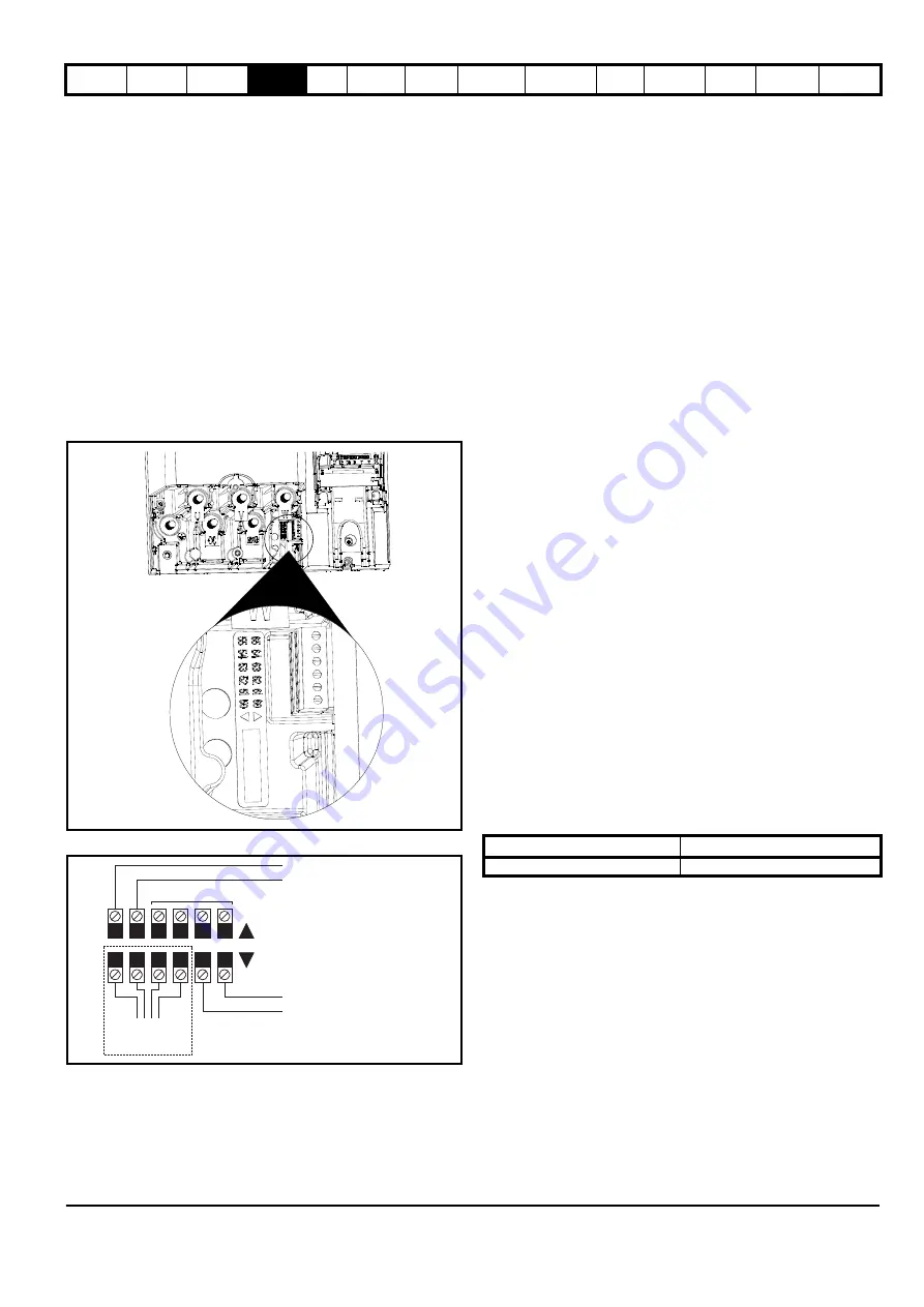
4.5.1 Heatsink fan supply
The heatsink fan on size 1 to 5 is supplied internally by the drive. The
heatsink fan on size 6 requires an external 24Vdc supply. The
connections for the heatsink fan supply must be made to the upper
terminal connector near to the W phase output on the drive. Figure 4-9
shows the position of the heatsink fan supply connections.
Figure 4-9 Location of the size 6 heatsink fan supply connections
Figure 4-10 Size 6 heatsink fan supply connections
The heatsink fan supply requirements are as follows:
Nominal voltage:
24Vdc
Minimum voltage:
23.5Vdc
Maximum voltage:
27Vdc
Current drawn:
3.3A
Recommended power supply: 24V, 100W, 4.5A
Recommended fuse:
4A fast blow (I
2
t less than 20A
2
s)
4.6 Control 24Vdc supply
The 24Vdc input has three main functions.
•
It can be used to supplement the drive’s own internal 24V when
multiple SM-I/O Plus modules are being used and the current drawn
by these modules is greater than the drive can supply. (If too much
current is drawn from the drive, the drive will initiate a 'PS.24V' trip)
•
It can be used as a back-up power supply to keep the control circuits
of the drive powered up when the line power supply is removed. This
allows any fieldbus modules or serial communications to continue to
operate.
•
It can be used to commission the drive when the line power supply is
not available, as the display operates correctly. However, the drive
will be in the UV trip state unless either line power supply or low
voltage DC operation is enabled, therefore diagnostics may not be
possible. (Power down save parameters are not saved when using
the 24V back-up power supply input.)
The working voltage range of the 24V power supply is as follows:
Maximum continuous operating voltage:
30.0 V
Minimum continuous operating voltage:
19.2 V
Nominal operating voltage:
24.0 V
Minimum start up voltage:
21.6 V
Maximum power supply requirement at 24V:
60 W
Recommended fuse:
3 A, 50 Vdc
Minimum and maximum voltage values include ripple and noise. Ripple
and noise values must not exceed 5%.
4.7 Ratings
The input current is affected by the supply voltage and impedance.
Typical input current
The values of typical input current are given to aid calculations for power
flow and power loss.
The values of typical input current are stated for a balanced supply.
Maximum continuous input current
The values of maximum continuous input current are given to aid the
selection of cables and fuses. These values are stated for the worst case
condition with the unusual combination of stiff supply with bad balance.
The value stated for the maximum continuous input current would only
be seen in one of the input phases. The current in the other two phases
would be significantly lower.
The values of maximum input current are stated for a supply with a 2%
negative phase-sequence imbalance and rated at the supply fault
current given in Table 4-2.
Table 4-2 Supply fault current used to calculate maximum input currents
55 54 53 52 51 50
65 64 63 62 61 60
To the heatsink fan
Pre-wired internally
0V
24V low voltage DC mode enable
Not used
0V
24V heatsink fan supply
Upper terminal connector
Lower terminal connector
Model
Symmetrical fault level (kA)
All
100
Содержание Affinity
Страница 274: ...0474 0000 05 ...


