Safety
Information
Product
Information
Mechanical
Installation
Electrical
Installation
Getting
Started
Basic
parameters
Running
the motor
Optimization
SMARTCARD
operation
PC tools
Advanced
parameters
Technical
Data
Diagnostics
UL Listing
Information
Affinity User Guide
221
Issue Number: 5 www.controltechniques.com
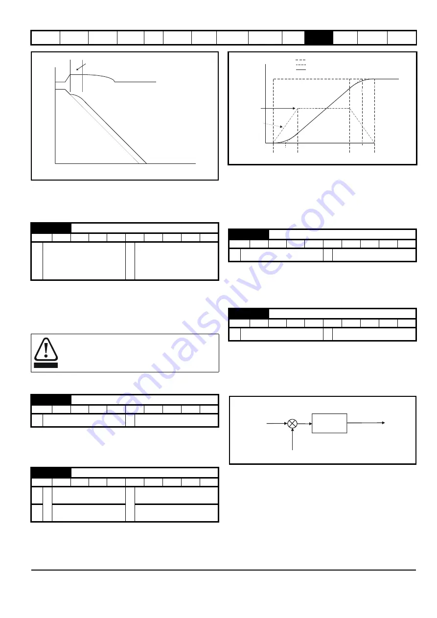
2: Standard ramp with motor voltage boost
This mode is the same as normal standard ramp mode except that the
motor voltage is boosted by 20%. This increases the losses in the motor
giving faster deceleration.
This voltage is used as the control level for standard ramp mode. If this
parameter is set too low the machine will coast to rest, and if it is set too
high and no braking resistor is used the drive may give an over-volt ‘OV’
trip. The minimum level should be greater than the voltage produced on
the DC bus by the highest supply voltage. Normally the DC bus voltage
will be approximately the rms supply line voltage x
√
2.
11.21.7 S ramps
Setting this parameter enables the S ramp function. S ramp is disabled
during deceleration using standard ramp. When the motor is accelerated
again after decelerating in standard ramp the acceleration ramp used by
the S ramp function is reset to zero.
This parameter defines the maximum rate of change of acceleration/
deceleration. The default values have been chosen such that for the
default ramps and maximum speed, the curved parts of the S will be
25% of the original ramp if S ramp is enabled.
Since the ramp rate is defined in s/100Hz or s/1000rpm and the S ramp
parameter is defined in s
2
/100Hz or s
2
/1000rpm, the time T for the
'curved' part of the S can be determined from:
T = S ramp rate of change / Ramp rate
Enabling S ramp increases the total ramp time by the period T since an
additional T/2 is added to each end of the ramp in producing the S.
11.21.8 Torque modes
Parameter for main torque reference. The normal update rate for the
torque reference is 4ms. However if analog inputs 2 or 3 on the drive are
used as the source of the reference, the drive is in RFC mode and the
analog inputs are in voltage mode with zero offset, the sample time is
reduced to 250
μ
s.
Open loop
If this parameter is 0 normal frequency control is used. If this parameter
is set to 1 the current demand is connected to the current PI controller
giving closed loop torque/current demand as shown below. The current
error is passed through proportional and integral terms to give a
frequency reference which is limited to the range: -SPEED_FREQ_MAX
to +SPEED_FREQ_MAX.
RFC
When this parameter is set to 1, 2 or 3 the ramps are not active while the
drive is in the run state. When the drive is taken out of the run state, but
not disabled, the appropriate stopping mode is used. It is recommended
that coast stopping or stopping without ramps are used. However, if
ramp stop mode is used the ramp output is pre-loaded with the actual
speed at the changeover point to avoid unwanted jumps in the speed
reference.
0: Speed control mode
The torque demand is equal to the speed loop output.
2.08
Standard ramp voltage
RW
Uni
RA
US
Ú
0 to
DC_VOLTAGE_SET_MAX V
Ö
200V drive: 375
400V drive: EUR> 750
USA> 775
575V drive: 895
690V drive: 1075
Care should be taken in the setting of this parameter. It is
recommended that the setting should be at least 50V higher
than the maximum expected level of the DC bus voltage. If
this is not done, the motor may fail to decelerate on a STOP
command.
2.06
S ramp enable
RW
Bit
US
Ú
OFF (0) or On (1)
Ö
OFF (0)
2.07
S ramp acceleration limit
RW
Uni
US
OL
Ú
0.0 to 300.0
s
2
/100Hz
Ö
3.1
RFC
0.000 to 100.000
s
2
/1000rpm
1.500
DC Bus voltage
Motor Speed
Programmed
deceleration
rate
t
Controller
operational
WARNING
4.08
Torque reference
RW
Bi
US
Ú
±USER_CURRENT_MAX %
Ö
0.00
4.11
Torque mode selector
RW
Uni
US
Ú
0 to 1
Ö
0
t
Acceleration
Actual Speed
Programmed
ramp rate
T
T
T/2
T/2
T/2
T/2
S ramp
acceleration
ramp
Demanded Speed
P Pr
4.13
I Pr
4.14
Current
demand
Active
current
Frequency
reference
+
-
Содержание Affinity
Страница 274: ...0474 0000 05 ...


