IL17569C
Page 5-26
FP-5000
Effective Date: 12/05
Page 5-26
For more information visit:
www.eatonelectrical.com
Effective Date: 12/05
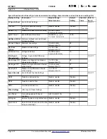
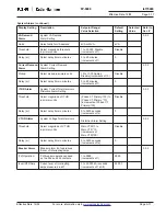
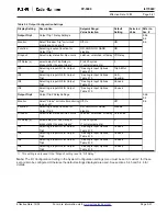
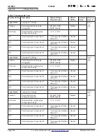
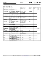
Table 5.7 Programmable Logic
Display Setting
Description
Setpoint Range/
Default
Selected
Refer to
Value Selection
Setting
Value
Sec. #
Logic Gate 1
Logic gate 1 Settings
5.5.7
9.3
Function:
Select logic function to apply
OR, AND, NOR,
Disable
9.6
to logic gate
NAND, Disable
Set Group:
Select protection setting group
1, 2, 3, 4 or All
1
for logic gate to apply
IN1:
Select logic type for logic input 1
* See Logic Input Options
Unused
Table 5.10
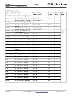
IN2:
Select logic type for logic input 2
* See Logic Input Options
Unused
Table 5.10
IN3:
Select logic type for logic input 3
* See Logic Input Options
Unused
Table 5.10
IN4:
Select logic type for logic input 4
* See Logic Input Options
Unused
Table 5.10
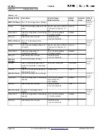
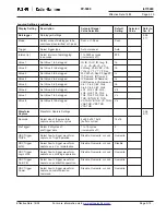
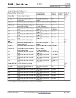
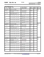
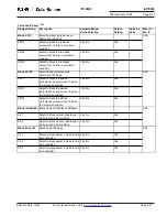
Logic Gate 2
Logic gate 2 Settings
5.5.7
9.3
Function:
Select logic function to apply
OR, AND, NOR,
Disable
9.6
to logic gate
NAND, Disable
Set Group:
Select protection setting group
1, 2, 3, 4 or All
1
for logic gate to apply
IN1:
Select logic type for logic input 1
* See Logic Input Options
Unused
Table 5.10
IN2:
Select logic type for logic input 2
* See Logic Input Options
Unused
Table 5.10
IN3:
Select logic type for logic input 3
* See Logic Input Options
Unused
Table 5.10
IN4:
Select logic type for logic input 4
* See Logic Input Options
Unused
Table 5.10
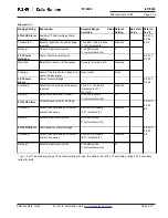
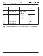
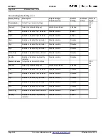
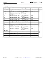
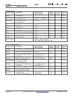
Logic Gate 3
Logic gate 3 Settings
5.5.7
9.3
Function:
Select logic function
OR, AND, NOR,
Disable
9.6
to apply to logic gate
NAND, Disable
Set Group:
Select protection setting group
1, 2, 3, 4 or All
1
for logic gate to apply
IN1:
Select logic type for logic input 1
* See Logic Input Options
Unused
Table 5.10
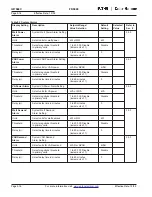
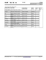
IN2:
Select logic type for logic input 2
* See Logic Input Options
Unused
Table 5.10
IN3:
Select logic type for logic input 3
* See Logic Input Options
Unused
Table 5.10
IN4:
Select logic type for logic input 4
* See Logic Input Options
Unused
Table 5.10

