


Page 14-2
For more information visit:
www.eatonelectrical.com
Effective Date: 12/05
IL17569C
Page 14-2
FP-5000
Effective Date: 12/05
D
Data Capture
8-15
Data Communications
10-1
Data Logging
8-15 - 8-16
Setpoints
8-15
Datalogger
5-50
Delta Voltage Transformers 8-10
Demand
4-8
Alarm
5-49
Current
5-49
VA
5-49
Var
5-49
Watt
5-49
Current
4-8, 5-49
Display
4-8
Power
4-8, 5-50
Device Numbers
13-4
Diagrams
Blocking Logic Gate
9-4
Close Breaker
8-13
CT Wiring Configuration
6-12
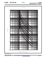
Curve with I
2
t Shape
8-5
Electronic Trip Curves
8-4
Four-Wire with IG CT
8-1
Four-Wire with IN CT
8-1
Instantaneous Setting Adjustment
8-6
Inverse Time Overcurrent Pickup
8-4
Loss of Potential
8-11
Open Breaker
8-13
Open Delta Application
2-4
with Sync-Check
2-5
Overall Logic Diagram
9-1
Phase Inverse Time Overcurrent Curve
5-42
Three-Wire CT Connection 8-1
Time Multiplier Adjustment 8-5
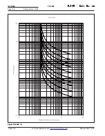
Time-Current Characteristic Curves
8-3
Voltage Delta Input Wiring Options with
Connection Schematics
6-9
with Sync-Check
6-10
Voltage Wye Input Wiring Option and
Connection Schematics
6-7
with Sync-Check
6-8
Wye Connected Application 2-2
with Sync-Check
2-3
Zone Interlocking
8-8
Dimensions
3-5
Disarm Control
5-40
Disarm Trip
9-4
Disclaimers
1-1
Discrete Input Sampling
8-1
Display
4-2
Modes
4-5
Sleep Mode
4-2
Disturbance Detection
8-15
Drawout Case
6-6 - 6-11
Dropout
5-52, 12-6
E
Energy
4-7
Display
4-7
Parameters
4-7
Energy Unit
5-40
Environmental Rating
3-5
Event
Clear Active Alarm
12-11
Log
4-21, 12-4 -
12-10
Display
4-22
Enable
5-50
F
Failures
12-1- 12-2
Detecting
12-15
Fault Simulation
11-3
Features
Communication
1-5
Control
1-4
Design
1-4
Mechanical
1-4
Metering
1-4
Monitoring
1-4
Protection
1-4
Self-Test
1-5
Firmware
12-15
Upgrading
12-20
FlashLoader
12-15 - 12-20
Forward Watthours
4-7
Frequency
Measurement
8-1
Frequency Protection
4-14, 5-39, 8-
10
Breaker Configuration
5-46
Overfrequency
5-46
Settings
5-45
Settings Table
8-11
Table
5-10
Underfrequency
5-45
Functions
Breaker
8-12
Fundamental Phasor
4-6
Display
4-6
G
Glossary
13-1 - 13-3
Ground Direction
5-41
IR Control
5-41
IX Control
5-42
Ground Fault Protection
8-6
Ground I
2
t Curve
13-18
Ground I
4
t Curve
13-17
Ground IT Curve
13-19
Ground Trip LED
4-23
H
Hardware
1-2
Help
12-15
History Log
4-22, 12-14
Breaker
4-22
Display
4-22
I
IEEE Standards
1-2, 3-5,
13-4
INCOM
2-6, 10-3
Inductive Load
4-7
Input Cause Table
12-8
Installation
6-1
Instantaneous Overcurrent 8-2
Blocking Logic Gates
5-53
IR IOC
5-44
IX IOC
5-44
Phase
5-44
Instantaneous Protection
8-6
Instantaneous Reset
8-2
Inverse Time-Overcurrent
Curve Shapes
8-3
Curves Table
8-3
Pickup Figure
8-4
Protection
8-2, 8-5
IPONI
Specifications
3-2
IR Ground Direction Control5-41
IR Residual OC
4-12, 5-44
Table
5-7
IX CT Ratio
5-39
IX Ground Direction Control5-42
IX Measured OC
4-12, 5-44
Table
5-6


