


Effective Date: 12/05
For more information visit:
www.eatonelectrical.com
Page 9-5
FP-5000
IL17569B
Page 9-5
Effective Date: 12/05
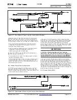
9.5 Logic Operation by the FP-5000
From the internal operation of the FP-5000, the pickup and operation
state of protective functions, system alarms, and breaker logic are
set as operation dictates and as described in other sections of this
manual (e.g. Inverse Time Overcurrent Pickup). The FP-5000
maintains a “Data Store” or image of the state of the outputs from
each function. The FP-5000 uses the value from the Data Store,
according to what the user has specified in the Setting Mode, to
determine the output state of each logic element. The user has a
selection of logical elements available that are connected together
by the use of programming references within the “Set Mode” rather
than with wires. The various logic gates and other logical elements
are “connected” together using symbolic references within the “Set
Mode.”
The logical elements are:
• Eight electrically isolated contact inputs (Cin1 – Cin8).
• A Zone Interlock input (Zin).
• Six flexible logic gates (LG1 – LG6).
• Six timer gates with programmable on delay and/or programmable
off delay (TG1 – TG6).
• Logic latches (Q1 – Q2).
• System status associated with Pickup and Timeout of protective
functions, operation of Monitoring Mode System Alarms, Breaker
monitoring and control, and communication logic states.
• Seven flexible Output logic gates (OGI – OG7).
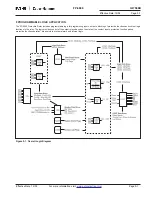
The FP-5000 functions are processed in the following order to
ensure proper and predictable operation of the logic functions.
1. One cycle values for rms and phasor quantities are computed.
2. The Contact Input states are read.
3. Logic Blocking Gate functions.
4. Protection functions.
5. Breaker monitoring and control functions.
6. Logic Gate, Timer Gate, and Latch functions LG1 – LG6, then
TG1 – TG6, then Q1 – Q2.
7. Logic Output Gate functions OG1 – OG7.
8. Output Relay logic routine.
Remember the programmed logic is evaluated sequentially, one
element at a time. Consequently, if this is not taken into account,
the user may encounter unexpected logic operation.
9.6 Programming Logic Functions
Some settings will so substantially change the structure of program-
ming that they force the user to make a choice to save immediately
and re-enter Set Mode in order to continue. The System Configuration
settings that permit Custom programming of the I/O Configuration
and Programmable Logic fall into this category.
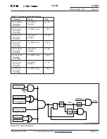
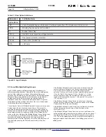
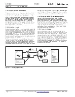
Programming logic consists of picking the logic gates as in any logic
design and connecting them together. Instead of signals, “Data Stores”
record the state of each of the important system parameters as of the
last determination or sampling. Instead of wires, logical name
references direct the FP-5000 code to obtain the logic input from a
particular Data Store. The computed outputs of the logic elements
are also saved. The stored results may be directed to additional logic
gate inputs until an output is directed to an output gate. Thus, the
user specified (or default) logic results in a relay contact closing
or opening.
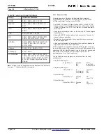
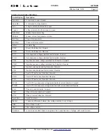
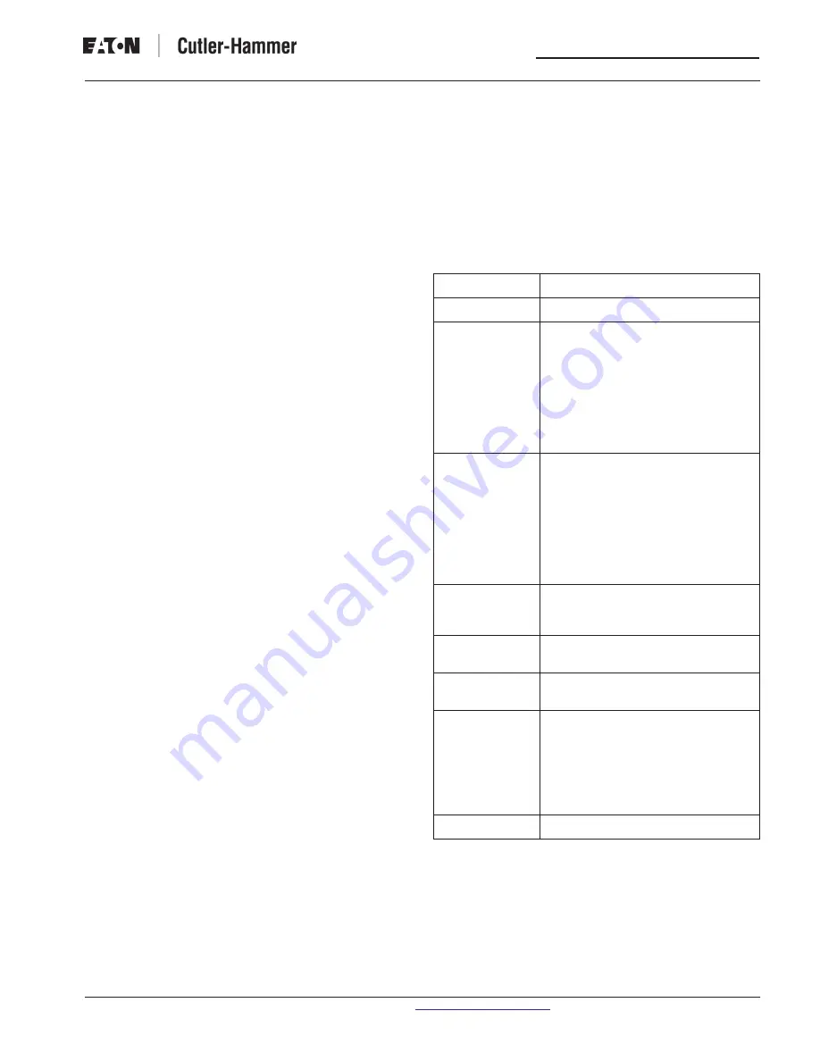
Table 9.4 Logic Elements Input Options
Input Category
Elements
Unused
Pickup
PH OC, G OC, IOC, TOC, OC, All Alm,
Volt, Freq, AllProt, 50X-1, 50X-2,
50X-3, 50R-1, 50R-2, 50R-3, 50P-2,
50P-3, 51P-1, 51P-2, 51P, 51X, 51R,
59A-1, 59A-2, 27A-1, 27A-2, 59M-1,
59M-2, 27M-1, 27M-2, 46-2, 47-1, 47-2,
81U-1, 31U-2, 81O-1, 81O-2, BF, 55A,
55D, 59N-1, 59N-2, 32-1, 32-2, 32-3,
LOP, LOPB
Trip
PH OC, G OC, IOC, TOC, OC, All Alm,
Volt, Freq, AllProt, 50X-1, 50X-2,
50X-3, 50R-1, 50R-2, 50R-3, 50P-2,
50P-3, 51P-1, 51P-2, 51P, 51X, 51R,
59A-1, 59A-2, 27A-1, 27A-2, 59M-1,
59M-2, 27M-1, 27M-2, 46-2, 47-1, 47-2,
81U-1, 31U-2, 81O-1, 81O-2, BF, 55A,
55D, PhZone, GndZone, 59N-1, 59N-2,
32-1, 32-2, 32-3, LOPA
Logic
LG1, LG2, LG3, L54, LG5, LG6, TG1,
TG2, TG3, TG4, TG5, TG6, OG1, OG2,
OG3, OG4, OG5, OG6, OG7
Inputs
Cin1, Cin2, Cin3, Cin4, Cin5, Cin6,
Cin7, Cin8 or ZI In
System Alarm
Power, Power Demand, Current
Demand, % THD, Bkr Ops,
Σ
I
Breaker Control
OpenBkr, CloseBkr, Open, Closed,
BkrFail Alm, StateAlm, Mntr1Alm,
Mntr2Alm, All Alm, 67G-F, 67G-R,
67V-F, 67V-R, 67Q-F, 67Q-R, 67I-F,
67I-R, 67X-F, 67X-R, 67VIXF, 67VIXR,
67A-F, 67B-F, 67C-F, InSync, SyncFail,
SlipAlm, 25BL, 25LL, Coldload
Communications
Comm1, Comm2, Comm3 or Comm4
The pickup and trip input categories provide selection of predefined
groups of protective functions. The definition of the individual
elements included in each group are shown in Table 9.5 Logic
Input Group Definitions.
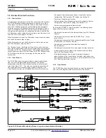
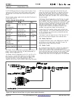
Programming of the logic functions is accomplished by selecting an
input category and element for each logic gate input. Input categories
include Unused, Pickup, Trip, Logic, Inputs, System Alarms, Breaker
Control, and Communications. The Pickup and Trip input categories
include selection of individual or groups of protective functions. The
System Alarm category provides selection of power, demand, THD,
and breaker operation functions. The Input category provides selection
of one of the eight contact inputs. The communications category
provides selection of any of the four communications logic states the
user may set true or false through the communication channel. Table
9.4 shows the elements available for each input category.


