Effective Date: 12/05
For more information visit:
www.eatonelectrical.com
Page 2-7
FP-5000
IL17569C
Page 2-7
Effective Date: 12/05
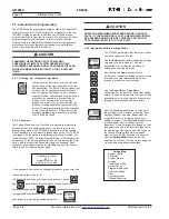
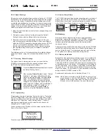
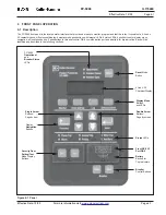
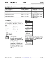
We will only be concerned with System Config and Protection
settings within the Quick Start section of this manual.
Select the category and press the Enter pushbutton to proceed. The
actual setting of values will be covered in Section 2.5.5.
2.5.4 Minimum Program Requirements
Default settings are provided to minimize the number of manual
programming steps for typical applications. For more complex
applications cases, the use of computer generated setting files
simplifies the setting process. The user programs through the RS-
232 front panel port by use of the PowerPort
TM
Windows
®
based or
PowerNet
TM
Software program. This subject is discussed in more
detail later in the manual.
2.5.5 Functions Which Must be Programmed
As stated earlier the FP-5000 comes pre-configured with default or
factory settings. The phase and ground overcurrent functions are
the only protection functions enabled and the current and voltage
unbalanced functions are the only alarm functions enabled. All
other protection and alarm functions are turned off and must be set
to enable their operation. The I/O comes pre-configured as default
from the factory for the most common applications. The I/O can be
changed per the requirements of the user’s application. The
current and voltage unbalanced alarms (46-2 and 47-2) are
enabled to assist the user in diagnosing any wiring problems.
For now we assume that the default settings will be adequate
except for the following list of functions, which the user must
program in order to handle the specific characteristics of your
system. Since only one protection setting Group is enabled, we
need only program the one group of protection settings and the
values necessary to define the proper operating environment of the
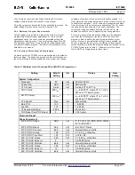
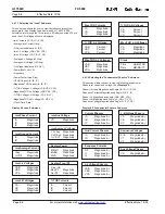
FP-5000. Please refer to Table 2.1 Minimum List of Functions
Which MUST be Programmed for those items.
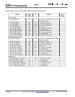
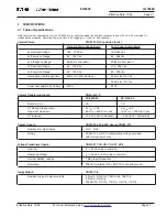
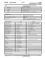
Table 2.1 Minimum List of Functions Which MUST be Programmed
Setting
Default
Setting
Incr
Display
User
Setting
Frequency:
60
List
50 Hz or 60 Hz
Phase Seq:
ABC
List
ABC or ACB
CT Connect:
3-wire
List
3-wire, 4CT In, 4CT Ig
PH CT Ratio:
500:I
nom
3
1
I
nom
to 6000:CT, where CT is 1 or 5 A
based on CT board jumper
NU CT Primary
500:I
nom
3
1
I
nom
to 6000:CT, where CT is 1 or 5 A
based on CT board jumper
VT Connect:
Wye
List
Wye or Delta
Main VTR:
100
1
1 to 8000
Aux VTR:
100
1
1 to 8000
VT Secondary Rating:
69.28
1
50 to 250 V
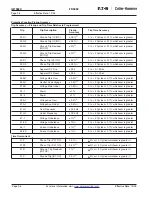
TOC Reset Time "TOC Reset
5
1
1-20 Cycles
51P PH TOC Shape:
MOD
List
IT, I2T, I4T, FLAT, MOD, VERY, XTRM,
IECA, IECB, IECC
51P PH TOC Reset:
Calc
List
Inst, Calc, T Delay
51P PH TOC Direction:
Both
List
Forward, Reverse, Both
51P PH TOC Pickup:
1.00
0.01
0.1 to 4.0
pu
or Disable
51P PH TOC Time Mult:
1.00
0.01
0.05 to 10.0
50P-1 PH IOC Pickup:
2.00
0.01
0.1 to 20.0
pu
or Disable
50P-1 PH IOC Delay (c):
0
1
0 to 9999 cycles
50P-1 PH IOC Direction:
Both
List
Forward, Reverse, Both
50P-2 PH IOC Pickup:
3.00
0.01
0.1 to 20.0
pu
or Disable
50P-2 PH IOC Delay (c):
15
1
0 to 9999 cycles
50P-1 PH IOC Direction:
Both
List
Forward, Reverse, Both
Protection/Group1
Phase Overcurrent
System Configuration


