


Effective Date: 12/05
For more information visit:
www.eatonelectrical.com
Page 5-53
FP-5000
IL17569C
Page 5-53
Effective Date: 12/05
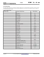
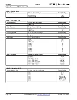
In:
This setting defines the logic input to Timer Gates
1 through 6. See the settings table and Section
9 for a complete description of the logic
input settings.
Delay Unit:
This setting selects if the delay is based on
cycles or seconds.
On Delay (c) :
Sets the number of cycles or seconds the
Timer Gate input must remain active before the
Timer Gate output becomes active. See Section
9 for a detailed description of the logic settings.
Off Delay (c) :
Sets the number of cycles or seconds the
Timer Gate output will remain active after the
Timer Gate input becomes inactive. The Off
Delay has no affect unless the Timer Gate
output is active when the input becomes
inactive. See Section 9 for a detailed descrip-
tion of the logic settings.
Logic Latches 1
Both logic latches contain the same settings as
and 2:
shown below.
Setting Group:
This setting defines the Setting Group for which
the logic latch programming is active. This setting
is also linked to the System Config settings, which
is where the total number of settings groups (1
to 4) is programmed.
Set In:
This setting defines the Set Input to the Logic
Latch. The latch output goes active when the
Set Input is active. The output remains latched
in the active state until the Reset is activated.
See the settings table and Section 9 for a
complete description of the logic input settings.
Reset In:
This setting defines the Reset Input to the Logic
Latch. The latch output is reset when the Reset
Input is active. If both the Set Input and Reset
Input are active, the latch output is inactive.
See the settings table and Section 9 for a
complete description of the logic input settings.
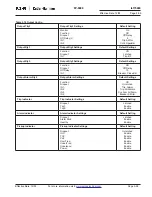
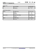
Blocking Logic
All 12 blocking logic gates contain the same
Gates for IOC
settings as shown below. When the output of
and TOC:
the blocking logic gate is active, operation of
the associated IOC or TOC protection function
is blocked. The IOC or TOC function will still
pickup, but not trip.
Function:
Set to OR, AND, NOR, NAND, Disable. The
Function setting defines the output of the blocking
logic gates with inputs IN1, IN2, IN3, and IN4.
The default setting is Disable. See Section 9 for
a detailed description of the logic settings.
Setting Group:
This setting defines the Setting Group for which
the logic gate programming is active. This setting
is also linked to the System Config settings,
which is where the total number of settings
groups (1 to 4) is programmed.
IN1, IN2, IN3, IN4:
These settings define the logic inputs to Logic
Gates 1 through 6. See the settings table and
Section 9 for a complete description of the
logic input settings.
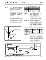
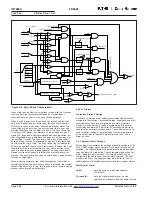
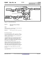
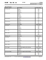
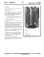
5.4.7 Programmable Logic Settings
The programmable logic settings consist of settings for six logic
gates, six timer gates, two latches, twelve blocking gates, and
seven output gates. The seven output gates (Output Trip1, Output
Trip2, Rly3, Rly4, Rly5, Output Alarm, and Output Aux LED) are
configured by the “Output Config” settings described previously,
therefore they won’t be discussed in this section.
See Section 9, Programmable Logic Application, for detailed
information about the logic functions. This section will only
describe how to set the programmable logic settings.
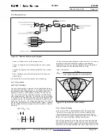
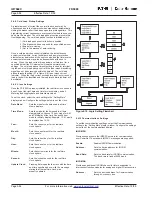
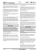
Figure 5-3
Logic Setting Flowchart, on the following page, shows an example
of how to program Logic Gate 1.
The
Figure 5-3
flowchart is an example of programming Logic
Gate 1 to be a NAND gate of setting group 2 with IN1 “Trip G OC.”
1. Select programmable Logic from the “Setting Main” setting
display menu and press “Enter PB.”
2. Select Logic Gate 1 press “Enter PB.”
3. Press “Enter PB” and choose Function to be NAND with up/
down PBs, press “Enter PB.”
4. Select Set Group using up/down PBs, press “Enter PB”, choose
Set Group to 2 using up/down PB’s, press “Enter PB.”
5. Select IN1 using up/down PBs, press “Enter PB.”
6. Select Trip using up/down PBs and press “Enter PB.”
7. Select G OC using up/down PBs and press “Enter PB.”
8. Select G OH to be Direct, then press “Enter PB”, which finishes
Logic Gate 1 programming.
Press “Previous PB” to back out of Logic Gate 1 programming and
return to “Programmable Logic” display to program other logic gates.
Logic Gates 1
All six logic gates contain the same
through 6:
settings as shown below.
Function:
Set to OR, AND, NOR, NAND, Disable. The
Function setting defines the output of the logic
gates with inputs IN1, IN2, IN3, and IN4. The
default setting is OR.
Setting Group:
This setting defines the Setting Group for
which
the logic gate programming is active.
This
setting is also linked to the System
Config
settings, which is where the total
number of
settings groups (1 to 4) is pro-
grammed.
IN1, IN2, IN3, IN4:
These settings define the logic inputs to Logic
Gates 1 through 6. See the settings table and
Section 9.6 for a complete description of the
logic input settings.
Timer Gates 1
All six timer gates contain the same settings as
through 6:
shown below.
Setting Group:
This setting defines the Setting Group for
which the timer gate programming is active.
This setting is also linked to the System Config
settings, which is where the total number of
settings groups (1 to 4) is programmed.


