IL17569C
Page 8-2
FP-5000
Effective Date: 12/05
Page 8-2
For more information visit:
www.eatonelectrical.com
Effective Date: 12/05
8.3 Overcurrent Functions – Instantaneous
and Time
8.3.1 Instantaneous
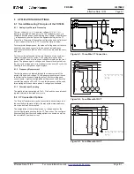
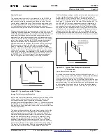
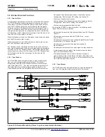
The Instantaneous Trip occurs when any of the phase currents
exceeds the pickup current defined by the user. That is:
I
phase
> I
pick up
Instantaneous Trip may be set for a delay from zero (0) to 9999
cycles after the pickup current is exceeded. Since the current is
evaluated twice per cycle, the initiation of the trip action begins
within a cycle for a setting of 0. Completion of the trip depends upon
the usual electromechanical contact output delays in the FP-5000
(included in specification of trip time accuracy) and in the time for the
breaker to open. The FP-5000 provides two timed or instantaneous
phase trip functions: 50P1 and 50P2. One of the trip functions can
be used as a truly instantaneous with zero delay while the other can
be used as a short delay function.
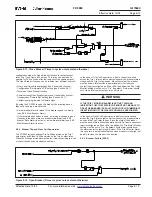
8.3.2 Inverse Time-Overcurrent Protection (51)
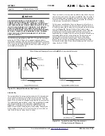
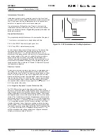
Three families of curves provide inverse time overcurrent protection.
The three families are: Thermal, ANSI and IEC curves. The FP-
5000 provides 10 standard Time overcurrent curves: Flat, It, I
2
t, and
I
4
t for Thermal; Extremely Inverse, Very Inverse and Moderately
Inverse for ANSI; and IEC-C, IEC-B and IEC-A for IEC.
Thermal
Thermal curves include It, I
2
t, I
4
t and FLAT, and are defined by the
following equation:
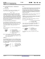
T
= Trip Time in Seconds
D
= Time Multiplier Setting
M = Slope (0=FLAT, 1= It, 2=I
2
t, 4=I
4
t)
K
= 3 for Phase, 1 for Ground
I
nom
= Nominal Current either 5 or 1 A
I
= Measured Current
Note:
The 5X multiplier in the FP-5000 Thermal Curve equation
means the phase trip time at 3 per unit current is 5 * D,
where D is the Time Multiplier setting. The ground trip time
at 1 per unit current is 5 * D.
ANSI & IEC
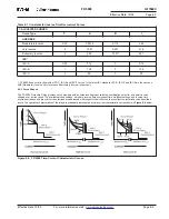
The ANSI Moderately Inverse, Very Inverse and Extremely Inverse
curves are defined by ANSI C37.112. The IEC curves are defined by
IEC 255-3. The ANSI and IEC families of curves are defined by the
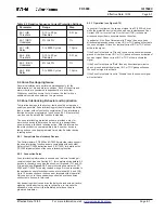
same equation and differ only in the selection of constants A, B and
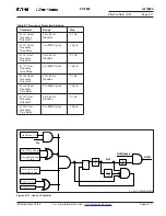
P as contained in Table 8.1. The trip time, T, in seconds is defined by
the following equation:
T
= Trip Time in seconds
D
= Time Multiplier Setting
I
pu
= Pickup Current Setting
I
= Measured Current
A, B, P = Constants
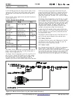
Reset
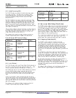
The reset function describes what occurs to the accumulated tally of
the TOC function if the current goes below pickup. The accumulated
tally is similar to how far an induction disk has traveled if an
electromechanical relay was being used. The time delayed reset
function provides improved coordination with electromechanical and
other relays. The reset function is very important if the breaker re-
closes quickly after tripping. The FP-5000 allows a choice of three
different reset functions:
Instantaneous Reset
– If the current is less than the programmed
pickup current, the accumulated memory is erased.
Time Delay
– This is exactly like the instantaneous reset except the
current must be below pickup for the set number of cycles before
the accumulated memory is removed.
Calculated
– For the thermal curves, the following reset time is
given to zero the accumulated memory:
t = Time to Reset Accumulated Memory
D = Time Multiplier Setting
K = 1 for Ground, 3 for Phase
Notice that the reset time is independent of the magnitude of the
current as long as the current magnitude is below pickup.
The reset function for the ANSI and IEC curves are given in the
following equations defined in ANSI C37.112. The constant t
r
is
defined in Table 8.1.
Gr = See Table 8.1
D
= Time Multiplier Setting
I
= Measured Current
I
pu
= Pickup Current Setting
The constants for the indicated curve equations are contained
in Table 8.1.

