IL17569B
Page 11-2
FP-5000
Effective Date: 12/05
Page 11-2
For more information visit:
www.eatonelectrical.com
Effective Date: 12/05
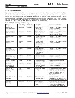
11.2.3.1 Verifying Current and Voltage Inputs
Using a current source provides a three-phase input current to the
current transformer input terminals (TB4). See Section 6 for phase
identification and wiring tips. Also provide a three-phase voltage
input to the unit under test. Refer to the FP-5000 time current
curves. Set the unit’s setpoints as desired and note the expected
trip time as indicated on the trip curve. Apply the test current and
note the start time. Select the “Monitor” button on the front panel
and verify the proper current and voltage inputs. Polarity and
phasing of the currents and voltages must be considered. Next,
note the trip time of the trip coil. The FP-5000 should trip within the
time indicated on the time current curves. For tolerances see the
Table of Specifications in Section 3.1.
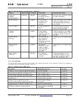
11.2.3.2 Verify Zone Interlock
Connect the contact of the Zone Interlock output to the contact of the
Zone Interlock input. Verify settings, input current and expected trip
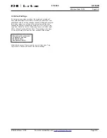
times as mentioned above in Section 11.2.3.1. In the View Settings
menu, verify the Zone Interlock is enabled. Test the unit by applying
current as in the test in 11.2.3.1. Trip times should be as indicated in
Table specification. Remove the short from Zone Interlock Out to
Zone Interlock In. Repeat the previous test. The trip times should be
much faster (around .050 seconds).
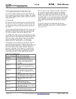
The Zone Interlock output can be checked through the use of the
“Test Zone Interlock” menu item from the test menu. A simple
voltmeter can be used for this test. This function is available under
the bottom lower protective cover labeled “Set” and “Test.” This
function is found under Test/Test Zone Interlock menu. You will have
a choice of “Turn on ZI Output” or “Reset ZI Output.” Move cursor and
press Enter to select either mode. Using a voltmeter, measure the
voltage on TB3 connector J3-1 and J3-2. A voltage of 4.5 to 5.0 volts
should be measured when on and then near zero when off.
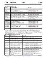
11.2.3.3 Testing Overvoltage and Undervoltage Protection
Under the View Settings menu, find the setting of both the
undervoltage and overvoltage protection. If the settings are not as
desired then modify it in the setting’s menu under Protection/Main V
Protection. Set the undervoltage to 60 volts and then the overvoltage
to 120 volts, both with no delay. Starting with 100 volts, apply the test
voltage to the voltage input terminals TB2 213-215. Decrease the
voltage input to just below 60 V and the unit should trip on
undervoltage, raise the voltage to just over 120 V and the FP-5000
should trip on overvoltage as expected.
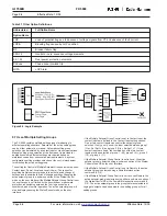
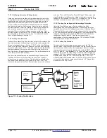
11.2.3.4 Testing Trip Monitors
The trip monitor feature status can be viewed under the “Status/
Control” menu - Input status/Trip # Monitor. The trip monitor circuits
can be tested on the bench by simply applying a fused ac voltage
source and series load across the trip relay contacts TB117 and 118
or TB115 and 116 – see
Figure 11.1
. The fuse and load should limit
current to stay within the relay rating in case the relay contacts are
engaged. A 120 Vac indicator lamp can serve this purpose. With the
trip relay open, apply the 120 V source to trip relay 1. The Trip 1
monitor display should indicate the “on” status. Remove the source
or close the relay and the status should indicate “off.” Repeat this
procedure for the Trip 2 relay.
Figure 11-1. Testing Trip Monitors
Breaker
Monitor
Circuit
Input
Impedance
~44k ohms
or 108k ohms
for 250V Power
Supply

