FP-5000
IL17569C
Page 7-1
Effective Date: 12/05
Effective Date: 12/05
For more information visit:
www.eatonelectrical.com
Page 7-1
7 STARTUP
General
— This section lists the procedure for applying power to
an FP-5000 for the first time. Use it as a checklist to reduce the
chance of skipping an item.
DANGER
ONLY QUALIFIED PERSONNEL FAMILIAR WITH THE FP-5000,
THE BREAKER, AND ITS ASSOCIATED MECHANICAL EQUIP-
MENT, SHOULD PERFORM THESE STARTUP PROCEDURES.
FAILURE TO COMPLY CAN RESULT IN SERIOUS OR FATAL
INJURY AND/OR EQUIPMENT DAMAGE.
CAUTION
NEVER HIGH POT THE FP-5000 CIRCUITS BEYOND
1500 VRMS/1 MIN. DO NOT USE A MEGGER
®
, HI-POT, OR
OTHER HIGH VOLTAGE INSULATION TESTER ON THE FP-5000
TERMINALS, IT HAS BEEN FACTORY TESTED, AND FIELD
TESTING MAY CAUSE UNNECESSARY STRESS. REMOVE THE
FP-5000 INNER CHASSIS WHEN TESTING THE PROTECTIVE
RELAY SYSTEM.
CAUTION
DO NOT USE A MEGGER
®
, HI-POT, OR OTHERWISE HIGH
VOLTAGE TO TEST THE FOLLOWING TERMINALS OR POINTS:
• TB3 - J1-3 SHIELD – IS BONDED TO HOUSING
(FILTER CLAMP)
• TB3 - J2-3 SHIELD – IS BONDED TO HOUSING
(FILTER CLAMP)
• TB3 - J3-5 SHIELD – IS BONDED TO HOUSING
(DIRECT GROUND)
• TB2 - 218 VG (REF.) – IS BONDED TO HOUSING
(FILTER CLAMP)
• FRONT RS-232 PROGRAMMING PORT SHELL – IS BONDED
TO HOUSING (DIRECT GROUND)
Startup consists of Programming the necessary operational
parameters, verifying the operation of the FP-5000, checking the
wiring, and verifying the reasonable operation of the system
components before attempting to place the equipment into
continuous service.
The programming should already be done before FP-5000 is placed
into service. Protection parameters may be reviewed in the View
Settings mode or adjusted in the Set Mode.
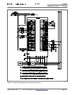
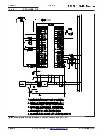
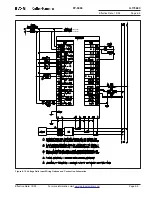
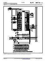
Refer to wiring
Figures 2-2
and
2-3
and
Figure 6-5
on terminal
definitions, Section 3 “Specifications” for nominal ratings during
startup.
7.1 Power-Off Checks
With the incoming ac distribution power locked off and after all
sources of power to the FP-5000 are de-energized, including
control system battery, check the wiring for conformance to the
wiring plan developed for the application.
• Verify that the CT secondary current rating and the FP-5000 CT
input rating style agree (either 5 A or 1 A). See Section 1.8
Ordering Information for catalog number identification.
• Verify that the Voltage Inputs are referenced to Voltage transform-
ers where the common is earth ground. TB2 Terminal 218 “Vg” is
internally bonded within the FP-5000 to protective earth and can
not be connected to neutral or a phase reference.
WARNING
VOLTAGE TRANSFORMERS ARE OFTEN CONNECTED “UP-
STREAM” FROM THE BREAKER CIRCUIT MONITORED AND SO
MAY BE DIFFICULT TO DISENGAGE.
7.2 Initial Control Power-On Checks
• All power sources should be disconnected as described in
Section 7.1.
• Disable all trip and control circuits.
• Disconnect and insulate the breaker trip coil load leads from any
of the trip relay terminals, typically Relay1 and Relay2 on TB1
terminals 116 and 118, to prevent breaker from energizing during
most of this testing.
• Disconnect and insulate any control circuit loads connected to the
remaining control relays on the FP-5000.
• Verify FP-5000 power supply control power:
– Disconnect the ac or dc control power lead to terminals
TB101(+).
– Connect a voltmeter to the circuit that fed TB101 and the
return on TB102.
– Energize the FP-5000 power supply power source
and monitor the voltage.
– Make sure that it is within nominal specifications:
– Battery system 48 – 125 Vdc or
control power transformer 100 – 120 Vac.
– For 250V power supply
Battey system 100-250 Vdc
Control power transformers 100-240 Vac
– De-energize the power supply source.
• Verify trip relay control voltage:
– Connect a voltmeter between each trip relay breaker trip coil
load wire just disconnected from terminal 116 or 118, and the
other meter lead to the control power source (TB115/117).
– Energize the trip coil source power.
– Measure the voltage and ensure that it is within the FP-5000
trip relay nominal specifications.
– De-energize the control power and troubleshoot
as necessary.
• Verify the FP-5000 Relay Health Alarm, Breaker Alarm and
any other auxiliary FP-5000 relay control circuit in the same
manner as the trip relay circuits.

