PMAC-Pack
PMACPack Mating and Connectors
71
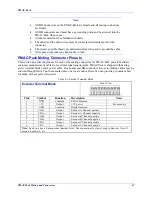
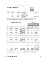
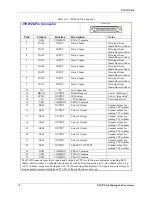
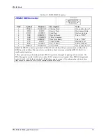
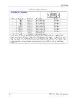
Table 6-8. FLT Relay Terminal Block
FLT Relay Terminal Block
Front View
Pin# Symbol Function
Description
Notes
1 NC
Output
Normally closed
FE/Watchdog output
See jumper E28
2 COM
Common
PMAC COMMON
3 NO
Output
Normally open
FE/Watchdog output
See jumper E28
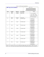
Note:
This 3 pin terminal block provides an output (either normally open, or, normally closed) for
FE/Watchdog timer monitoring. Jumper E28 determines the functionality of this output.
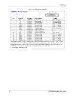
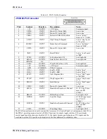
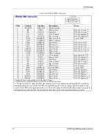
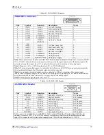
Table 6-9. TBAMP Terminal Block
TBAMP Terminal Block
Front View
Pin# Symbol Function
Description
ALT
Symbol
ALT
Function
ALT
Description
1 STEP
1
OUTPUT
1
st
Motor Pulse
(ref to Step GND)
OUT1+
Output
1st motor + lead
2 DIR
1 OUTPUT
1
st
Motor Direction
(ref to Step GND)
OUT1-
Output
1st motor - lead
3 STEP
2 OUTPUT 2
nd
Motor Pulse
(ref to Step GND)
OUT2+
Output
2nd motor +
lead
4 DIR
2 OUTPUT
2
nd
Motor Direction
(ref to Step GND)
OUT2-
Output
2nd motor -
lead
5 STEP
3 OUTPUT 3
rd
Motor Pulse
(ref to Step GND)
OUT3+
Output
3rd motor +
lead
6 DIR
3 OUTPUT
3
rd
Motor Direction
(ref to Step GND)
OUT3-
Output
3rd motor - lead
7 STEP
4 OUTPUT 4
th
Motor Pulse
(ref to Step GND)
OUT4+
Output
4th motor +
lead
8 DIR
4 OUTPUT
4
th
Motor Direction
(ref to Step GND)
OUT4-
Output
4th motor - lead
9
No Connect
No Connect
DB R-
Output
External shunt
reg. resistor; not
less than 10
Ω
10
No Connect
No Connect
DB R+
Output
External shunt
reg. resistor; not
less than 10
Ω
11
STEP GND
COMMON
Signal Return
PGND
Common
Bus Vground
12
STEP +V
INPUT
Optional Supply
(+5V to +24V)
A+48V
Input
DC bus supply
Note:
This terminal block provides connection of pulse and direction outputs for stepper axes or alternately
for either of PMAC-Pack's internal amplifier accessories (ACC8D OPT4PP or ACC8D OPT4APP).
Connection points are provided for motor leads, optional shunt regulator resistor, and amplifier power
supply.
Содержание PMAC Pack
Страница 10: ...PMAC Pack Table of Contents vii ...
Страница 11: ......
Страница 16: ...PMAC Pack Overview 5 Figure 1 1 PMAC Pack Dimension ...
Страница 27: ...PMAC Pack 16 Overview ...
Страница 47: ...PMAC Pack 36 Getting Started ...
Страница 51: ...PMAC Pack 40 Complying with European Community EMC Requirements ...
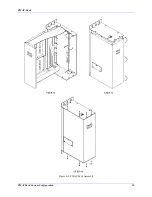
Страница 53: ...PMAC Pack 42 PMACPack Custom Configuration Figure 4 1 PMAC Pack Disassembly ...
Страница 70: ...PMAC Pack PMACPack Custom Configuration 59 Figure 4 4 PMAC Pack Assembly ...
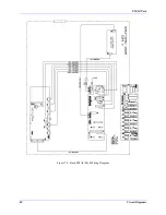
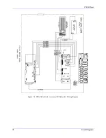
Страница 91: ...PMAC Pack 80 Circuit Diagrams Figure 7 2 Basic PMAC Pack Wiring Diagram ...
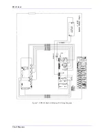
Страница 92: ...PMAC Pack Circuit Diagrams Figure 7 3 PMAC Pack with Accessory 8D Option 2 Wiring Diagram ...
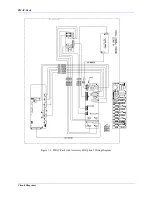
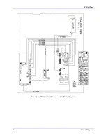
Страница 93: ...PMAC Pack 82 Circuit Diagrams Figure 7 4 PMAC Pack with Accessory 8D Option 4A Wiring Diagram ...
Страница 94: ...PMAC Pack Circuit Diagrams Figure 7 5 PMAC Pack with Option 9L Wiring Diagram ...
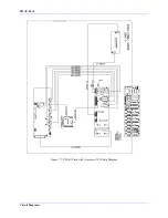
Страница 95: ...PMAC Pack 84 Circuit Diagrams Figure 7 6 PMAC Pack with Accessory 28A Wiring Diagram ...
Страница 96: ...PMAC Pack Circuit Diagrams Figure 7 7 PMAC Pack with Accessory 39 Wiring Diagram ...
Страница 97: ...PMAC Pack 86 Circuit Diagrams ...
Страница 98: ...PMAC Pack Circuit Diagrams 87 ...
Страница 99: ...PMAC Pack 88 Circuit Diagrams ...
Страница 100: ...PMAC Pack Circuit Diagrams 89 ...
Страница 101: ...PMAC Pack 90 Circuit Diagrams ...
Страница 103: ...92 Acc 24E Acc 24EXP Expansion XP Pack Figure 8 1 Expansion Pack Installation ...
Страница 106: ...PMAC Pack Acc 24E Acc 24EXP Expansion XP Pack 95 Figure 8 3 PMAC Pack Assembly ...
Страница 109: ...98 Acc 24E Acc 24EXP Expansion XP Pack ...
Страница 117: ...106 PMACPack Options and Accessories ...

