PMAC-Pack
18
Getting
Started
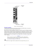
Figure 2-1. PMAC-Pack Mounting
Power Connection
Connect the power cord provided to the power port on the front of the PMACPack. A strain relief is
provided underneath the power plug and should be utilized.
PMAC-Pack's auto-ranging internal power supplies can accept 85 to 265 VAC (47-63Hz). The plug on
the end of the power cord is a standard 115 VAC plug. If you are connecting to other than 115 VAC, or
find it necessary to extend the cord, cut the plug from the power cord and proceed to connect to your AC
input source. When AC power is applied to the PMAC-Pack, the controller's green PWR LED should
illuminate. The red WDT LED (watch dog timer) should not light. Provided this is the case, proceed to
Installing the PMAC Executive Program below. If the WDT LED is lit, consult the Troubleshooting
Guide in Chapter 4.
Caution:
Make sure the Power Cord's AC Ground connection is intact. PMAC-Pack's
Chassis Ground is provided by this connection. Failure to Ground the AC Power
line could result in damage to the PMAC-Pack.
PMAC-Pack is shipped with both a standard U.S and a European format power cord.
Содержание PMAC Pack
Страница 10: ...PMAC Pack Table of Contents vii ...
Страница 11: ......
Страница 16: ...PMAC Pack Overview 5 Figure 1 1 PMAC Pack Dimension ...
Страница 27: ...PMAC Pack 16 Overview ...
Страница 47: ...PMAC Pack 36 Getting Started ...
Страница 51: ...PMAC Pack 40 Complying with European Community EMC Requirements ...
Страница 53: ...PMAC Pack 42 PMACPack Custom Configuration Figure 4 1 PMAC Pack Disassembly ...
Страница 70: ...PMAC Pack PMACPack Custom Configuration 59 Figure 4 4 PMAC Pack Assembly ...
Страница 91: ...PMAC Pack 80 Circuit Diagrams Figure 7 2 Basic PMAC Pack Wiring Diagram ...
Страница 92: ...PMAC Pack Circuit Diagrams Figure 7 3 PMAC Pack with Accessory 8D Option 2 Wiring Diagram ...
Страница 93: ...PMAC Pack 82 Circuit Diagrams Figure 7 4 PMAC Pack with Accessory 8D Option 4A Wiring Diagram ...
Страница 94: ...PMAC Pack Circuit Diagrams Figure 7 5 PMAC Pack with Option 9L Wiring Diagram ...
Страница 95: ...PMAC Pack 84 Circuit Diagrams Figure 7 6 PMAC Pack with Accessory 28A Wiring Diagram ...
Страница 96: ...PMAC Pack Circuit Diagrams Figure 7 7 PMAC Pack with Accessory 39 Wiring Diagram ...
Страница 97: ...PMAC Pack 86 Circuit Diagrams ...
Страница 98: ...PMAC Pack Circuit Diagrams 87 ...
Страница 99: ...PMAC Pack 88 Circuit Diagrams ...
Страница 100: ...PMAC Pack Circuit Diagrams 89 ...
Страница 101: ...PMAC Pack 90 Circuit Diagrams ...
Страница 103: ...92 Acc 24E Acc 24EXP Expansion XP Pack Figure 8 1 Expansion Pack Installation ...
Страница 106: ...PMAC Pack Acc 24E Acc 24EXP Expansion XP Pack 95 Figure 8 3 PMAC Pack Assembly ...
Страница 109: ...98 Acc 24E Acc 24EXP Expansion XP Pack ...
Страница 117: ...106 PMACPack Options and Accessories ...


