96
Acc-24E Acc-24EXP Expansion XP Pack
Encoder Conversion Table Setup
To read encoders interfaced into the Expansion Pack, PMAC’s encoder conversion table must be set up to
read and process the encoder signals. To set up the Encoder Conversion Table, use the PMAC
Executive’s menu-based encoder table setup, which is accessed from the
CONFIGURE
menu. For entries 5
through 8, change the
SOURCE ADDRESS
to encoders 9 through 12. When finished, your table should look
as follows:
Entry
Address
Y-Word
(Source
Address)
Conversion Method
1
Y:$720
$00C000
1/T extension of encoder 1 at $C000
2
Y:$721
$00C004
1/T extension of encoder 2 at $C004
3 Y:$722 $00C008
Q
4
Y:$723
$00C00C
1/T extension of encoder 4 at $C00C
5
Y:$724
$00C020
1/T extension of encoder 9 at $C020
6
Y:$725
$00C024
1/T extension of encoder 10 at $C024
7
Y:$726
$00C028
1/T extension of encoder 11 at $C028
8
Y:$727
$00C02C
1/T extension of encoder 12 at C02C
Once the encoder conversion table is set, the encoder setup for axes 5 through 8 is completed. The factory
default settings for Ix03, Ix04, and Ix05 will now apply for encoder-to-axis feedback mapping.
Motor Output Command Setup
The Ix02 variable in PMAC is used to tell PMAC where (what address) to map the output command for
motor x. The outputs for axes 5 through 8 must be mapped into DACs 9 through 12.
For non-commutated axes (
)
10V torque or velocity output commands) set:
•
I502 = $C023 (DAC 9)
•
I602 = $C022 (DAC 10)
•
I702 = $C02B (DAC 11)
•
I802 = $C02A (DAC 12)
For commutated axes (2 sinusoidal phase output commands per axis) set:
•
Ix02 = $C022 (DACs 9 and 10)
•
Ix02 = $02A (DACs 11 and 12)
Flag Input Command Setup
The Ix25 variable is used by PMAC to determine what set of inputs it will look to for motor x’s
overtravel limit switches, home flag, amplifier-fault flag, and amplifier enable output. Typically, these are
the flags associated with an encoder input; specifically those of the position feedback encoder for the
motor. It is necessary to reassign the Ix25 variables for motors 5 through 8 to correspond to the flag set
associated with encoders 9 through 12. Flag source address settings are as follows:
•
LIM9, HMFL 9,…$C020
•
LIM10, HMFL 10,…$C024
•
LIM11, HMFL11,…$C028
•
LIM12, HMFL12,…$C02C
Содержание PMAC Pack
Страница 10: ...PMAC Pack Table of Contents vii ...
Страница 11: ......
Страница 16: ...PMAC Pack Overview 5 Figure 1 1 PMAC Pack Dimension ...
Страница 27: ...PMAC Pack 16 Overview ...
Страница 47: ...PMAC Pack 36 Getting Started ...
Страница 51: ...PMAC Pack 40 Complying with European Community EMC Requirements ...
Страница 53: ...PMAC Pack 42 PMACPack Custom Configuration Figure 4 1 PMAC Pack Disassembly ...
Страница 70: ...PMAC Pack PMACPack Custom Configuration 59 Figure 4 4 PMAC Pack Assembly ...
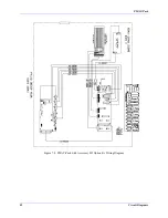
Страница 91: ...PMAC Pack 80 Circuit Diagrams Figure 7 2 Basic PMAC Pack Wiring Diagram ...
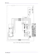
Страница 92: ...PMAC Pack Circuit Diagrams Figure 7 3 PMAC Pack with Accessory 8D Option 2 Wiring Diagram ...
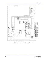
Страница 93: ...PMAC Pack 82 Circuit Diagrams Figure 7 4 PMAC Pack with Accessory 8D Option 4A Wiring Diagram ...
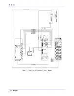
Страница 94: ...PMAC Pack Circuit Diagrams Figure 7 5 PMAC Pack with Option 9L Wiring Diagram ...
Страница 95: ...PMAC Pack 84 Circuit Diagrams Figure 7 6 PMAC Pack with Accessory 28A Wiring Diagram ...
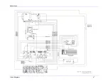
Страница 96: ...PMAC Pack Circuit Diagrams Figure 7 7 PMAC Pack with Accessory 39 Wiring Diagram ...
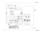
Страница 97: ...PMAC Pack 86 Circuit Diagrams ...
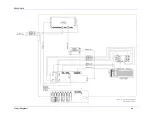
Страница 98: ...PMAC Pack Circuit Diagrams 87 ...
Страница 99: ...PMAC Pack 88 Circuit Diagrams ...
Страница 100: ...PMAC Pack Circuit Diagrams 89 ...
Страница 101: ...PMAC Pack 90 Circuit Diagrams ...
Страница 103: ...92 Acc 24E Acc 24EXP Expansion XP Pack Figure 8 1 Expansion Pack Installation ...
Страница 106: ...PMAC Pack Acc 24E Acc 24EXP Expansion XP Pack 95 Figure 8 3 PMAC Pack Assembly ...
Страница 109: ...98 Acc 24E Acc 24EXP Expansion XP Pack ...
Страница 117: ...106 PMACPack Options and Accessories ...

