background image


PMAC-Pack 

54 


PMACPack Custom Configuration 

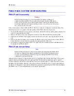
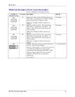
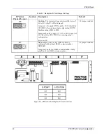
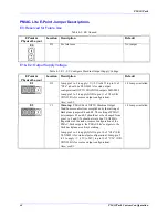
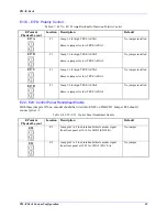
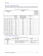
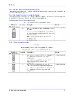
E49: Serial Communications Parity Control 

Table 4-17. E49: Serial Communications Parity Control 

E Point & 

Physical Layout 

Location Description 

Default 

E49 


C2


Jump pin 1 to 2 for NO serial parity; remove jumper for 
ODD serial parity. 


Jumper installed


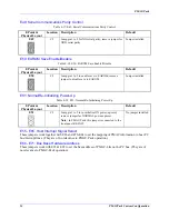
E50: EAROM Save Enable/Disable 

Table 4-18. E50: EAROM Save Enable/Disable 

E Point & 

Physical Layout 

Location Description 

Default 

E50 


C2


Jump pin 1 to 2 to enable save to EAROM; remove 
jumper to disable save to EAROM. 


Jumper installed


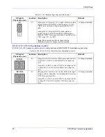
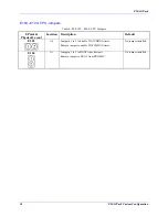
E51: Normal/Re-Initializing Power-Up 

Table 4-19. E51: Normal/Re-Initializing Power-Up 

E Point & 

Physical Layout 

Location Description 

Default 

E51 


C2


Jump pin 1 to 2 to re-initialize ON power-up/reset; 
remove jumper for NORMAL power-up/reset. 

Note:  

In PMAC-Pack, this jumper is connected to the 

front panel RE-INIT.


No jumper installed


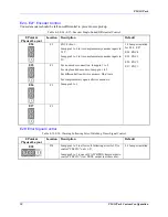
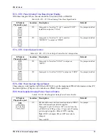
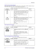
E55 - E65: Host Interrupt Signal Select 

These jumpers work together with E86 and E76-E84 to set the mapping of PMAC information to host PC 
bus interrupt lines. (They are of no relevance to PMAC-Pack operation.) 

E66 - E71: Bus Base Hardware Address 

These jumpers work with E91 & E92 to set the base address of PMAC-Lite on the PC bus. (They are of 
no relevance to PMAC-Pack operation). 

Содержание PMAC Pack

Страница 1: ...l service in house repair center WE BUY USED EQUIPMENT Sell your excess underutilized and idle used equipment We also offer credit for buy backs and trade ins www artisantg com WeBuyEquipment REMOTE INSPECTION Remotely inspect equipment before purchasing with our interactive website at www instraview com LOOKING FOR MORE INFORMATION Visit us on the web at www artisantg com for more information on ...

Страница 2: ...CE MANUAL 2 PMAC Pack 3 Box PMAC Lite PC 4 3xx 602476 xHxx 5 June 2003 Single Source Machine Control Power Flexibility Ease of Use 21314 Lassen Street Chatsworth CA 91311 Tel 818 998 2095 Fax 818 998 7807 www deltatau com ...

Страница 3: ...d amplifiers contain static sensitive components that can be damaged by incorrect handling When installing or handling Delta Tau Data Systems Inc products avoid contact with highly insulated materials Only qualified personnel should be allowed to handle this equipment In the case of industrial applications we expect our products to be protected from hazardous or conductive materials and or environ...

Страница 4: ... and Indicators 13 Enhancements 14 ACC 24EXP Expansion Pack 15 GETTING STARTED 17 Quick Start Guide Non Commutated Motors 17 Inspection 17 Jumper Setup 17 Mounting 17 Power Connection 18 Installing the PMAC Executive Program 19 Communication SwitchBank Setup 19 S1 S4 Software Address Control 19 S5 S8 Communications Control 20 Serial Port Connection 21 Establishing Communications 21 Terminal Mode C...

Страница 5: ...er Setup 41 PMAC Pack Backplane E Point Jumper Descriptions 43 PMAC Lite E Point Jumper Descriptions 46 PMAC Pack Re assembly 60 TROUBLESHOOTING 61 PMAC PACK MATING CONNECTORS AND PINOUTS 65 PMAC Pack Mating Connectors 65 Connector Name Type Function and Part Numbers 65 PMAC Pack Mating Connector Pinouts 67 CIRCUIT DIAGRAMS 79 ACC24E ACC24EXP EXPANSION XP PACK 91 Expansion Pack Installation 91 PMA...

Страница 6: ...Servo Evaluation Package 102 Accessory 26 Serial Communications Converter 102 Accessory 27 Optically Isolated I O Board 103 Accessory 29 Magnetostrictive Linear Displacement Transducer Interface Board 103 Accessory 31 PMAC Demonstration Box Unit 103 Accessory 32 PMAC Software Upgrade Update Kit 104 Accessory 34 Multiplexed I O Expansion Board 104 Accessory 35 Multiplexer Port Extender Modules 104 ...

Страница 7: ...e Connector Installation 3 3 Figure 4 1 PMAC Pack Disassembly 4 2 Figure 4 2 PMAC Pack Backplane E Point Locations 4 4 Figure 4 3 PMAC Lite E Point Locations 4 5 Figure 4 4 PMAC Pack Assembly 4 20 Figure 7 1 PMAC Pack System Connections Basic Non Commutated System 7 1 Figure 7 2 Basic PMAC Pack Wiring Diagram 7 2 Figure 7 3 PMAC Pack with Accessory 8D Option 2 Wiring Diagram 7 3 Figure 7 4 PMAC Pa...

Страница 8: ...hdog Timer Signal Control 4 10 Table 4 11 E29 E33 Phase Clock Frequency Control 4 11 Table 4 12 E34 E38 Encoder Sampling Clock Frequency Control 4 11 Table 4 13 E39 Reset From Bus Enable 4 12 Table 4 14 E40 E43 Software Address Control 4 12 Table 4 15 E44 E47 Communications Control 4 13 Table 4 16 E48 Cpu Clock Frequency Control 4 14 Table 4 17 E49 Serial Communications Parity Control 4 14 Table 4...

Страница 9: ...Table 6 7 JOPT Input Terminal Block 6 6 Table 6 8 FLT Relay Terminal Block 6 7 Table 6 9 TBAMP Terminal Block 6 7 Table 6 10 JDISP 14 Pin Connector 6 8 Table 6 10 JDISP 14 Pin Connector 6 9 Table 6 11 JPAN 26 Pin Connector 6 9 Table 6 11 JPAN 26 Pin Connector 6 10 Table 6 12 JTHW 26 Pin Connector 6 10 Table 6 13 JRS232 DB9 Connector 6 12 Table 6 14 JRS422 DB25 Connector 6 12 Table 6 15 JANA DB15 C...

Страница 10: ...PMAC Pack Table of Contents vii ...

Страница 11: ......

Страница 12: ...This chapter contains all data required to comply with Council Directive 89 336 EEC relating to Electromagnetic Compatibility Chapter 4 PMAC Pack Custom Configuration This chapter describes how to disassemble the PMAC Pack set the E Point jumpers on the PMAC Pack backplane and PMAC Lite card and reassemble the PMAC Pack This Chapter also describes how to prevent electrostatic discharge ESD damage ...

Страница 13: ...C User s Manual 3A0 602204 xSxx PMAC PMAC2 Software Reference 3A0 602274 xHxx PMAC Lite Hardware Reference Manual 3A0 0PEWIN xUxx PMAC Executive for Windows User s Manual PEWIN Safety Summary The following are general safety precautions not related to any specific procedures and therefore may not appear elsewhere in this publication These are recommended precautions that personnel must understand ...

Страница 14: ...tors et al We invite you to use this service You can download upload files and read posted bulletins and Delta Tau newsletters Messages may be left for anyone who is a member user of the Bulletin Board System s All you need is a modem and Procomm Plus or similar communications program Many Download Upload Protocols such as Z Modem are supported Our BBS is also linked to the Delta Tau Internet site...

Страница 15: ...g 11 lb PMAC Pack standard 6 1 kg 13 4 lb PMAC Pack w all available Opt Acc 4 2 kg 9 25 lb PMAC Pack Expansion Box standard Temperature Operating 0oC to 60oC 32oF to 140oF Storage 12oC to 82oC 10oF to 180oF Humidity 10 to 95 non condensing Electrical Specifications Internal Power Requirements Eight channel configuration with a typical load of encoders 1 5A 5V 5 7 5W 0 3A 12 to 15V 4 5W 0 25A 12 to...

Страница 16: ...PMAC Pack Overview 5 Figure 1 1 PMAC Pack Dimension ...

Страница 17: ...h firmware for master control program RAM 384 Kbytes at 0 wait state static 128K 24 bit words for active memory battery backed User Program Storage 42K words X1000 Y1000 is two words 256KBytes EAROM 2KBytes EEPROM non volatile memory for setup parameter storage 384 Kbytes flash backup for non volatile user parameters programs definitions and tables CPU Specifications Type and Clock Speed Standard ...

Страница 18: ...s Minimum of 110 microseconds 8 axes Phasing Algorithm Suitable for permanent magnet brushless motors AC induction motors switched reluctance servo motors microstepped stepping motors 2 3 or 4 phase motors Y wound delta wound or electrically independent phases Block Execution Rate 100 500 blocks moves per second with full trajectory calculation depending upon particular program conditions Approxim...

Страница 19: ...Sockets provided for termination resistor packs Input rate DC to 20mHz count rate X1 X2 X4 decoding or pulse and direction Digital delay filter for removing noise spikes 3rd channel input available for position capture Unused counters available as timers Absolute Encoders Thru accessory of 14D I O Expansion card or other binary parallel word position data source Can be up to 12 absolute parallel e...

Страница 20: ...s shipped socketed IC replaceable with sourcing driver Serves as amplifier enable signal or direction bit Polarity is settable by hardware jumper E17 Uncommitted lines may be used as general purpose optically isolated digital outputs General Purpose Digital Inputs Jopto 8 general purpose opto isolated digital inputs 0 24V levels Sink or source normally high or normally low configuration determined...

Страница 21: ...L output lines Designed for interface to ACC 18 Thumb wheel Multiplexer board s up to 512 digits or 2048 discrete inputs ACC 34 multiplexed I O card s provide expanded I O interface Note The thumbwheel Multiplexer port may also be used as general purpose multiplexed I O Display Outputs Connector to standard 2x24 or 2x40 character alpha numeric liquid crystal or vacuum fluorescent display Expansion...

Страница 22: ...ce User defined address offset bit width decode Operators For use in user programs add subtract multiply divide modulo bit by bit AND bit by bit OR bit by bit XOR Comparators For use in conditional statements in programs equal to not equal to greater than not greater than less than not less than approximately equal to not approximately equal to Functions For use in user programs SIN COS TAN ASIN A...

Страница 23: ...rop communications to several PMACs on single serial line ACC8D OPT 2PP 4 Channel Voltage to Frequency Converter for use with stepper motor pulse and direction drives ACC8D OPT 4PP 40 W 4 Channel linear amplifier for hydraulic valves ACC8D OPT 4APP 150 W 4 Channel PWM amplifier for small DC brush motors ACC26APP Serial Communications Isolator and Converter ACC28APP 4 Channel 16 bit A D Converter c...

Страница 24: ...e PMAC packs on single serial cable Requires PMACPACK OPT 9LPP JRS232 port is rendered non functional JANA 15 Pin D Sub Connector Analog input port connector only active when PMAC Pack is equipped with ACC28PP Provides interface for 4 analog inputs isolated power JEXP 50 Pin Box Header Expansion port for connection of ACC24EXP PMAC ACC14 or other PMAC accessories which connect directly to the micr...

Страница 25: ...e sequenced with relay logic On power up 5V supply stabilizes prior to enabling 12V analog supplies A Reinitialization switch momentary contact only active on power up has been added to the front panel to allow reinitialization without disassembly Opto Isolation has been added to PMAC Pack s JOPT machine I O JOPT IN JOPT OUT FLAGS FLT RELAY and TBAMP connections have been improved Opto Isolation h...

Страница 26: ...may be ordered with the internal accessories shown in Table 1 3 Note When PMAC is used to commutate Brushless or AC Induction motors 2 DAC channels per axis are required Refer to the PMAC User s manual for further details on PMAC motor commutation Table 1 3 Expansion Pack Options and Accessories Option Accessory Number Definition ACC 8D OPT2EXP 4 Channel Voltage to Frequency Converter For use with...

Страница 27: ...PMAC Pack 16 Overview ...

Страница 28: ...rd U S and European format power cords Jumper Setup PMAC Pack has numerous pairs of metal prongs called E Points The way in which these metal prongs are either shorted together jumpered or left open determines the board hardware configuration A listing of these E points is provided in Chapter 3 The vast majority of applications can be accomplished using the default settings thereby eliminating the...

Страница 29: ...he cord cut the plug from the power cord and proceed to connect to your AC input source When AC power is applied to the PMAC Pack the controller s green PWR LED should illuminate The red WDT LED watch dog timer should not light Provided this is the case proceed to Installing the PMAC Executive Program below If the WDT LED is lit consult the Troubleshooting Guide in Chapter 4 Caution Make sure the ...

Страница 30: ...C Lite jumpers E40 E43 These jumpers in turn control the software address of the card for serial addressing and for sharing the servo clock over the serial connector Card 0 address 0 sends the clock and cards 1 F receive the clock Refer to Table 2 1 for address control settings Note Unless your system contains multiple PMAC packs daisy chained on a single serial cable S1 S4 should always be ON The...

Страница 31: ...PANEL S5 S6 S7 S8 20 MHz Flash CPU OPT 4A Standard 20 MHz Battery backed CPU standard on units produced prior to AUG 1 1995 or 40 MHz Flash CPU OPT 5A 60 MHz Flash CPU OPT 5B ON ON ON ON DISABLED DISABLED DISABLED OFF ON ON ON 300 600 900 ON OFF ON ON 400 800 1200 OFF OFF ON ON 600 1200 1800 ON ON OFF ON 800 1600 2400 OFF ON OFF ON 1200 2400 3600 ON OFF OFF ON 1600 3200 4800 OFF OFF OFF ON 2400 48...

Страница 32: ...the program where and how to communicate with PMAC it will attempt to establish communications with PMAC Pack by sending a query command and waiting for the response If it gets the expected type of response it will report that it has found PMAC and you will be able to proceed If it does not get the expected type of response after several attempts it will report that it has not found PMAC Note Inst...

Страница 33: ... that each PMAC Axis is mapped to the desired Encoder Connect the A and B quadrature encoder channels to the appropriate terminal block pins The PMAC Pack is setup by default for either single ended or differential Line Driver encoders If you have a single ended signal leave the complementary signal pins floating do not ground them If you are using an encoder with complementary open collector outp...

Страница 34: ...e In this setup leave the DAC1 pin pin 6 floating do not ground it Differential Command Signal For a differential command using PMAC channel 1 connect DAC1 pin 5 to the plus command input on the amplifier Connect DAC1 pin 6 to the minus command input on the amplifier PMAC s AGND pin 4 should still be connected to the amplifier common Figure 2 3 PMAC Pack Amplifier Pinouts Amplifier Enable Signal A...

Страница 35: ...OSLIM PMAC Pack has two inputs for each motor intended for the hardware overtravel limit switches These lines must actively be held low to draw current through the optoisolator in order for the motor to be able to move This requires the use of normally closed or normally conducting if solid state limit switches These inputs are direction sensitive they only stop movement in one direction The PMAC ...

Страница 36: ...for a specific application Many of these are used to configure a motor properly Once set up these variables may be stored in nonvolatile EAROM memory using the SAVE command so the card is always configured properly PMAC loads the EAROM I variable values into RAM on power up Connect power to your PMAC Pack only At this time do not power your amplifiers Run your PMAC Executive Program on the PC The ...

Страница 37: ...ilter for noise spike elimination is turned on PMAC is shipped with the filters on I901 I906 0 I902 I907 I912 Etc Encoder Position Capture Control These I variables control which transitions of which associated encoder signals trigger a position capture for that encoder This must be used for homing moves it can also be used for other purposes It specifies an edge of the encoder third channel the e...

Страница 38: ...s we have connected we must set I102 address C003 49155 decimal This is the default value Refer to the PMAC Software Reference Manual 3A0 602204 363 for a complete address listing of all DACs Ix03 Position Loop feedback address Variable Ix03 defines the register to be used for the position loop servo feedback Typically this reads a processed encoder value from what is known as the encoder conversi...

Страница 39: ...nse If the motor does not move or if you encounter a polarity mismatch refer to the Troubleshooting Guide in Chapter 4 Testing the Command Output and Polarity Next we will check the command outputs and whether the output polarity matches the feedback polarity To do this we will need to provide power to our amplifier First have PMAC disable its own outputs for the motor by typing K CR kill Make sur...

Страница 40: ...e reasonable stiffness but do not try yet to get the maximum possible stiffness The tests described below will help you do that Oscillations If the motor has a tendency to oscillate at low to moderate frequency you probably have inadequate derivative gain Try doubling I131 and see if the oscillation goes away Buzzing If the motor has a tendency to oscillate at high frequency a buzz you probably ha...

Страница 41: ...ed loop control issue the J command Optimizing Jog Performance If your jog speed seems slower than you want you may have run into one or more of PMAC s automatic safety limit parameters particularly if you have a fine resolution system The first of these is I119 which is the maximum permitted motor jog acceleration expressed in counts msec2 The default value is quite low for most systems You may w...

Страница 42: ...ing or sourcing Jumpers E1 E2 and E7 on the PMAC Lite Card should never be changed from pins 1 2 PMAC Pack s JOPT INPUT and JOPT OUTPUT connectors provide eight general purpose digital inputs and eight general purpose digital outputs Each I O point is opto isolated and designed for direct connection to 12 to 24V I O For basic familiarization with PMAC Pack s machine I O you can use a 2 position sw...

Страница 43: ... the PMAC Pack backplane is socketed and so may easily be replaced For this driver internal 3 3Kohm pull resistors keep the outputs from floating A typical interconnection is shown in Figure 2 7 With a UDN2981 driver IC PMAC Pack Backplane Jumper E4 must connect pins 2 and 3 and Jumper E5 must connect pins 2 and 3 Field Configurable or order as factory Option 14APP The orange Opto Isolation Power ...

Страница 44: ...nput in a Sinking configuration and Figure 2 9 illustrates the connection of an input in sourcing configuration When the switch is closed current flows through the switch and into the PMAC Pack s opto isolator to the Limit Return which is tied to common When the switch is closed current is pulled through the opto isolator in the PMAC PACK to ground The general purpose inputs are capable of operati...

Страница 45: ...ce at Y address FFC2 Setup M Variables to point at the specific I O points bits of Y FFC2 as shown in Table 2 3 Testing the I O Testing an Output Using the terminal window of the PMAC Exec type M01 0 CR Now type M01 1 CR You should see the LED or corresponding device interfaced to Machine Output 1 pin 11 change state Type M01 0 CR again The device should return to the original state Testing an Inp...

Страница 46: ...Outputs 1 8 treated as byte M11 Y FFC2 0 1 Machine Input 1 M12 Y FFC2 1 1 Machine Input 2 M13 Y FFC2 2 1 Machine Input 3 M14 Y FFC2 3 1 Machine Input 4 M15 Y FFC2 4 1 Machine Input 5 M16 Y FFC2 5 1 Machine Input 6 M17 Y FFC2 6 1 Machine Input 7 M18 Y FFC2 7 1 Machine Input 8 M19 Y FFC2 0 8 U Machine Inputs 1 8 treated as byte Coordinate Systems and Programming Your basic system setup is now comple...

Страница 47: ...PMAC Pack 36 Getting Started ...

Страница 48: ... the following instructions will comply with Council Directive 89 336 EEC relating to electromagnetic compatibility EN50081 2 EN55011 Class A Group 1 EN50082 2 EN61000 4 2 ENV50140 ENV50204 EN61000 4 4 ENV50141 Cable Fabrication There are several types of cables and connectors that can be used to install PMAC Pack in accordance with CE requirements No matter which type of cables and connectors are...

Страница 49: ...PMAC Pack installation are dedicated cable with foil wrap and braided shielding twisted shielded cable flat shielded cable and flat cable in a twist with shield Figure 3 2 demonstrates the proper installation and grounding for these types of cable Signal Cables The exposed portion of signal cable shielding must be kept to a minimum nominally 10 to 12 mm If a backshell is being used Delta Tau recom...

Страница 50: ...PMAC Pack Complying with European Community EMC Requirements 39 Figure 3 2 Typical Cable Connector Installation ...

Страница 51: ...PMAC Pack 40 Complying with European Community EMC Requirements ...

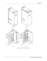
Страница 52: ...emove the three mounting screws securing the PMAC Lite motion control card as shown PMAC Lite is then free to swivel outward exposing the component side of the card 5 Set jumpers as required Jumpers E40 47 are replaced by the communications SwitchBank on the front panel of the PMAC Pack PMAC Pack Jumper Setup Note Delta Tau Data Systems Inc does not recommend reconfiguring the PMAC Pack All units ...

Страница 53: ...PMAC Pack 42 PMACPack Custom Configuration Figure 4 1 PMAC Pack Disassembly ...

Страница 54: ...A port for power of analog inputs Defeats isolation Note If E2 is changed E1 and E3 must also be changed No jumper E3 F4 Jumps pin 1 to pin 2 to allow 12V to come from PMAC Pack s internal supply Ties PMAC 12V supply to JANA port for power of analog inputs Defeats isolation Note If E3 is changed E1 and E2 must also be changed No jumper E4 Caution The jumper settings must match the type of driver I...

Страница 55: ...ld be ULN2803A for sinking output configuration JOPTO Machine outputs M01 to M08 Jump pins 2 and 3 to apply V 12 to 24V to pin 9 of U10 should be UDN 21981 for sourcing output configuration Also see E1 1 2 jumper installed E7 Note Jumper is only active if PMAC Pack is configured with optional RS422 communications OPT9LPP Jump pins 1 and 2 for RS485 communications Jump pins 2 and 3 for RS422 commun...

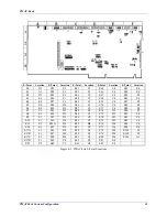
Страница 56: ...4 E87 F4 E5 E4 E28 D4 E46 C3 E70 C4 E88 F4 E6 E4 E29 D3 E47 C3 E71 C4 E89 F3 E7 C1 E31 D3 E48 C2 E72 D2 E90 F3 E8 E1 E32 D3 E49 C2 E73 D2 E91 C4 E9 E1 E33 D3 E50 C2 E74 D2 E92 C4 E10 E1 E34 D4 E51 C2 E75 D2 E93 C4 E13 E1 E34A D4 E55 B4 E76 D4 E94 C4 E14 E1 E35 D4 E57 C4 E77 D4 E98 D4 E17A F1 E36 D4 E58 C4 E78 D4 E101 F1 E17B F1 E37 D4 E59 C4 E79 D4 E102 F2 E17C F1 E38 D4 E61 C4 E80 D4 E103 A1 E17D...

Страница 57: ...pply GND to pin 11 of U26 S B UDN2981A for source output configuration Also see E2 1 2 Jumper installed E2 C3 Warning PMAC Pack JOPTO Machine Output Sink Source control is accomplished by the setting of Backplane jumpers E4 and E5 The setting of PMAC Lite jumpers E1 and E2 should never be changed from pins 1 to 2 and U26 should always be a ULN2803A Regardless of the sink or source configuration of...

Страница 58: ...ample time greater than one millisecond the sampling may be slowed in software with variable Ix60 Frequency can be checked on J4 pins 21 22 Note If E40 E43 are set up so that the card has a software address other than 0 the servo clock signal must be received over the serial port from card 0 so these jumpers have no effect Table 4 4 E3 E6 Servo Clock Frequency Control E3 E4 E5 E6 Servo Clock Phase...

Страница 59: ... 2 Jumper installed E9 E10 E13 E14 Handshake Control E9 E10 E13 E14 jumpers control various configurations of RS422 RS232 handshake signal setup Table 4 6 E9 E10 E13 E14 Serial Interface Handshake Control E Point Physical Layout Location Description Default E9 E10 E1 Jump E9 1 to E9 2 to allow TXD to be input on J4 3 jump E10 1 to E10 2 to allow RXD to be output on J4 5 Jump E9 1 to E10 1 to allow...

Страница 60: ...emove jumper for low TRUE AENA3 No jumper installed E17D F1 Jump 1 2 for high TRUE AENA4 Remove jumper for low TRUE AENA4 No jumper installed E22 E23 Control Panel Handwheel Enable With these jumpers ON no encoder should be wired into ENC2 on JMACH1 Jumper E26 should connect pins 1 2 Table 4 8 E22 E23 Control Panel Handwheel Enable E Point Physical Layout Location Description Default E22 E2 Jump p...

Страница 61: ... For no encoder connection Jump pin 1 to 2 For single ended encoders Jump pin 1 to 2 For differential line driver encoders Don t care For complementary open collector encoders Jump pin 2 to 3 1 2 Jumper installed for E24 E27 E24 ENC 4 E25 ENC 3 E26 ENC 2 E27 ENC 1 E28 Error Signal Control Table 4 10 E28 Warning Following Error Watchdog Timer Signal Control E Point Physical Layout Location Descript...

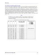
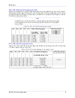
Страница 62: ...33 19 6608MHz Master Clock 29 4912 MHz Master Clock Default Physical Layout E33 E32 E31 E30 E29 ON OFF OFF OFF OFF 2 26 kHz 3 39 kHz OFF ON OFF OFF OFF 4 52 kHz 6 78 kHz OFF OFF ON OFF OFF 9 04 kHz 13 55 kHz OFF OFF OFF ON OFF 18 07 kHz 27 10 kHz OFF OFF OFF OFF ON 36 14 kHz 54 21 kHz E34 E38 SLCK Frequency Control Jumpers E34 E38 control the encoder sampling clock SCLK used by the gate array ICs ...

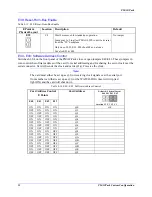
Страница 63: ...addressing and for sharing the servo clock over the serial connector Card 0 sends the clock and cards 1 F receive the clock Note The card must either be set up as 0 or receiving clock signals over the serial port from another card that is set up as 0 or the WATCH DOG timer will trip red light ON and the card will shut down Table 4 14 E40 E43 Software Address Control Card Address Control E Points E...

Страница 64: ...DISABLED OFF ON ON ON 300 600 900 ON OFF ON ON 400 800 1200 OFF OFF ON ON 600 1200 1800 ON ON OFF ON 800 1600 2400 OFF ON OFF ON 1200 2400 3600 ON OFF OFF ON 1600 3200 4800 OFF OFF OFF ON 2400 4800 7200 ON ON ON OFF 3200 6400 9600 OFF ON ON OFF 4800 9600 14400 ON OFF ON OFF 6400 12800 19200 OFF OFF ON OFF 9600 19200 28800 ON ON OFF OFF 12800 25600 38400 OFF ON OFF OFF 19200 38400 57600 ON OFF OFF ...

Страница 65: ... installed E51 Normal Re Initializing Power Up Table 4 19 E51 Normal Re Initializing Power Up E Point Physical Layout Location Description Default E51 C2 Jump pin 1 to 2 to re initialize ON power up reset remove jumper for NORMAL power up reset Note In PMAC Pack this jumper is connected to the front panel RE INIT No jumper installed E55 E65 Host Interrupt Signal Select These jumpers work together ...

Страница 66: ...n 1 to 2 to allow SCLK to output on CHC4 No jumper installed E75 D2 Jump pin 1 to 2 to allow SCLK to output on CHC4 No jumper installed E76 E84 Host Interrupt Signal Select These jumpers work together with E86 and E55 E65 to set the mapping of PMAC information to host PC bus interrupt lines They are of no relevance to PMAC Pack operation E85 Host Supplied Analog Power Source Enable Table 4 22 E85 ...

Страница 67: ...s 5 logic and 15 analog power supplies together Defeats OPTO coupling Note If E88 is changed E85 andE87 must also be changed Also see E90 No jumper E89 Switch Pull Up Enable Table 4 24 E89 Amplifier Supplied Switch Pull Up Enable E Point Physical Layout Location Description Default E89 F3 Jump pin 1 to 2 to allow A 15V V on PMAC LITE J8 JEQU pin 9 to tie to A 15V on J11 JMACH1 pin 59 This jumper m...

Страница 68: ...K signal to DACs and ADCs Important for high accuracy A D conversion on accessory boards Note This also divides the phase and servo clock frequencies in half See E29 E33 E3 E6 1 2 Jumper installed E101 E102 Output Configure Caution Improper setting of E101 or E102 will damage the output IC Table 4 27 E101 E102 Amplifier Enable Output Configure E Point Physical Layout Location Description Default E...

Страница 69: ... E104 CPU Jumpers E Point Physical Layout Location Description Default E103 A2 Jump pin 1 to 2 to disable WATCHDOG timer Remove jumper to enable WATCHDOG timer No jumper installed E104 A1 Jump pin 1 to 2 to BOOT from host port Remove jumper to BOOT from PROM IC No jumper installed ...

Страница 70: ...PMAC Pack PMACPack Custom Configuration 59 Figure 4 4 PMAC Pack Assembly ...

Страница 71: ...ting screws to secure PMAC Lite to the case Check that all internal connections are secure 2 Fold the left half of the PMAC Pack casing into the right First insert the rear lip of the left half into the back of the case Rotate the left half of the case until it is flush with the right You may need to pull the left halve slightly forward to clear the front right lip 3 Insert eight 8 sheet metal scr...

Страница 72: ...PC is being used Make sure that the Executive program is addressing the COM port and that you have cabled out of that COM port connector Check that the baud rate specified in the Executive program matches the baud rate setting on the PMAC Pack communications SwitchBank With a breakout box or oscilloscope make sure that you see action on the transmit lines from the PC as you type into the Executive...

Страница 73: ...l change the positive direction of the axis if you do not wish to do this you will need to exchange the motor leads instead The Motor Does Not Move Issue an O10 command to the motor which will not move Check the voltage on the output pin It should be approximately 1V relative to AGND If the DAC voltage HAS changed Recheck your amplifier and motor connections If the DAC voltage has not changed Rech...

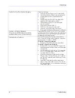
Страница 74: ...can output adequate voltage Can an integrator help Try increasing integral gain Ix33 to 10 000 or more and the integration limit Ix63 to 8 000 000 Runaway Condition Check the following Do you have feedback Check that you can read position changes in both directions Does your feedback polarity match output polarity Recheck the polarity match as explained above Brief Movement Then Stop Warning The f...

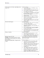
Страница 75: ...Not Change Check the following Verify with a voltmeter or scope that the input voltage is indeed changing 0 to 12 24Vdc as measured on Pin 11 Is the PMAC M Var that you are toggling linked to the address of the Machine Output Type M11 CR and verify that PMAC responds with Y FFC2 0 1 ...

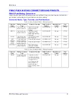
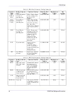
Страница 76: ...t input 016 P00006 08P Phoenix 1777329 FLAGS 5 pin female screw terminal connector Axis overtravel limit home flag inputs 016 P00005 08P Phoenix 1777316 JOPT OUTPUT 11 pin female screw terminal connector 8 General purpose outputs 016 P000011 08P Phoenix 1777374 JOPTO INPUT 11 pin female screw terminal connector 8 General purpose inputs 016 P000011 08P Phoenix 1777374 FLT RELAY 3 pin female screw t...

Страница 77: ...JEXP 50 pin box header Expansion port for connection of ACC24EXP PMAC ACC14 or other PMAC accessories which connect directly to the microprocessor bus 014 R00F50 0K0 AMP 609 5041 JHW 9 pin DB male connector Inputs for one channel of incremental quadrature encoder feedback 014 R00M09 ODB AMP 747306 4 Table 6 2 PMAC Pack Connectors Mating Connectors Connector Name Mating Connector Type Connector Fun...

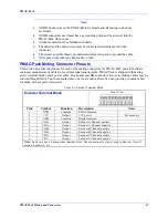
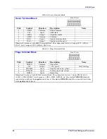
Страница 78: ... meet individual requirements PMAC Pack is shipped with mating screw terminal blocks and a power cable Box header and DB connectors for use in making cables may be sourced through Delta Tau the manufacturer or a local vendor Delta Tau can provide pre made cables for many of these ports if required Table 6 3 Encoder Terminal Block Encoder Terminal Block Front View Pin Symbol Function Description No...

Страница 79: ...xis 2 maps to FLT2 AENA2 DAC2 etc Table 6 5 Flags Terminal Block Flags Terminal Block Front View Pin Symbol Function Description Notes 1 FRETN Common Flag return 2 12V Output 12V power Only for flags 3 NEGLIM Input Negative end of travel limit 4 POSLIM Input Positive end of travel limit 5 HOME Input Home flag Note Each Axis has a 5 pin FLAGS terminal block The connections for Axis 1 map to PMAC Li...

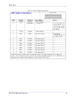
Страница 80: ...Output Machine Output 8 If sinking out LOW TRUE If source out HIGH TRUE 5 MO7 OUTPUT Machine Output 7 6 MO6 OUTPUT Machine Output 6 7 MO5 OUTPUT Machine Output 5 8 MO4 OUTPUT Machine Output 4 9 MO3 OUTPUT Machine Output 3 10 MO2 OUTPUT Machine Output 2 11 MO1 OUTPUT Machine Output 1 Note This connector provides means for eight general purpose outputs Outputs may be configured to provide 5Vto 24V s...

Страница 81: ... HIGH TRUE 6 MI6 Input Machine input 6 If sinking out LOW TRUE If source out HIGH TRUE 7 MI5 Input Machine input 5 If sinking out LOW TRUE If source out HIGH TRUE 8 MI4 Input Machine input4 If sinking out LOW TRUE If source out HIGH TRUE 9 MI3 Input Machine input 3 If sinking out LOW TRUE If source out HIGH TRUE 10 MI2 Input Machine input 2 If sinking out LOW TRUE If source out HIGH TRUE 11 MI1 In...

Страница 82: ...p GND OUT2 Output 2nd motor lead 4 DIR 2 OUTPUT 2nd Motor Direction ref to Step GND OUT2 Output 2nd motor lead 5 STEP 3 OUTPUT 3rd Motor Pulse ref to Step GND OUT3 Output 3rd motor lead 6 DIR 3 OUTPUT 3rd Motor Direction ref to Step GND OUT3 Output 3rd motor lead 7 STEP 4 OUTPUT 4th Motor Pulse ref to Step GND OUT4 Output 4th motor lead 8 DIR 4 OUTPUT 4th Motor Direction ref to Step GND OUT4 Outpu...

Страница 83: ...MMON PMAC Common 10 Vee OUTPUT Contrast Adjust Vee 0 to 5Vdc 11 R W OUTPUT Read or Write TTL Signal Out 12 DB0 OUTPUT Display Data0 TTL Signal Out 13 DB2 OUTPUT Display Data2 TTL Signal Out 14 DB4 OUTPUT Display Data4 TTL Signal Out 15 DB6 OUTPUT Display Data6 TTL Signal Out The JDISP connector is used to drive the 2 line x 24 character Acc 12 2 x 40 Acc 12A LCD the 2 x 40 vacuum fluorescent Acc 1...

Страница 84: ...C Common 15 JOG INPUT Jog IN DIR Low is jog 16 JOG INPUT Jog IN DIR Low is jog 17 STRT INPUT Start Program Run Low is start equiv to R CMD 18 STOP INPUT Stop Program Run Low is stop equiv to A 19 HOLD INPUT Hold Motion Low is hold equiv to H 20 FPD3 INPUT Motor C S Select Bit 3 Low is true 21 HWCA INPUT Handwheel Encoder A Channel 5V TTL SQ Pulse must use E23 CHA2 22 BRLD OUTPUT Buffer Request Ind...

Страница 85: ... GND COMMON PMAC Common 15 SEL0 OUTPUT Select 0 Output Scanner output for reading TW switches 16 SEL1 OUTPUT Select 1 Output Scanner output for reading TW switches 17 SEL2 OUTPUT Select 2 Output Scanner output for reading TW switches 18 SEL3 OUTPUT Select 3 Output Scanner output for reading TW switches 19 SEL4 OUTPUT Select 4 Output Scanner output for reading TW switches 20 SEL5 OUTPUT Select 5 Ou...

Страница 86: ...PMAC ready bit 9 SERVO IN OR OUT Servo Clock Out on 0 else in Note The JRS232 connector provides the PMAC Pack with the ability to communicate serially with an RS232 port In addition this connector is used to daisy chain interconnect multiple PMAC Pack s for synchronized operation These pins are for synchronizing multiple PMACs together by sharing their phasing and servo clocks The PMAC designated...

Страница 87: ...ue 16 SD OUTPUT Send Data Diff I O high true 17 CS INPUT Clear To Send Diff I O low true 18 RS OUTPUT Req To Send Diff I O low true 19 INIT INPUT PMAC Reset Low is reset 20 DSR BIDIRECT Data Set Ready Tied to DTR 21 SDIO BIDIRECT Special Data Diff I O high true 22 SCIO BIDIRECT Special Ctrl Diff I O high true 23 SCK BIDIRECT Special Clock Diff I O high true 24 SERVO BIDIRECT Servo Clock Diff I O h...

Страница 88: ...single ended inputs it is advisable to tie these pins to AGND for increased noise immunity If using differential inputs the differential return should be connected Note 3 As standard an isolated supply must be connected to JANA for isolation of the analog inputs PMAC Pack backplane jumpers E1 E2 and E3 are not jumped By jumping E1 E2 and E3 isolation may be bypassed and PMAC Pack s internal 15 V s...

Страница 89: ...ow is true 8 AENA4 OUTPUT Amp 4 Enable Dir Low is true 9 A V INPUT Flag Supply Volt 10 AGND COMMON Analog Flag Common This connector found on the PMAC LITE card brings out the 4 compare equal and 4 Amplifier Enable signals associated with PMAC Lite s channels 1 to 4 In addition the A V supply 12V to 24V for motor flags 1 to 4 may be brought in through this connector with PMAC Lite E89 OFF and E90 ...

Страница 90: ...PMAC Pack Circuit Diagrams CIRCUIT DIAGRAMS Figure 7 1 PMAC Pack System Connections Basic Non Commutated System ...

Страница 91: ...PMAC Pack 80 Circuit Diagrams Figure 7 2 Basic PMAC Pack Wiring Diagram ...

Страница 92: ...PMAC Pack Circuit Diagrams Figure 7 3 PMAC Pack with Accessory 8D Option 2 Wiring Diagram ...

Страница 93: ...PMAC Pack 82 Circuit Diagrams Figure 7 4 PMAC Pack with Accessory 8D Option 4A Wiring Diagram ...

Страница 94: ...PMAC Pack Circuit Diagrams Figure 7 5 PMAC Pack with Option 9L Wiring Diagram ...

Страница 95: ...PMAC Pack 84 Circuit Diagrams Figure 7 6 PMAC Pack with Accessory 28A Wiring Diagram ...

Страница 96: ...PMAC Pack Circuit Diagrams Figure 7 7 PMAC Pack with Accessory 39 Wiring Diagram ...

Страница 97: ...PMAC Pack 86 Circuit Diagrams ...

Страница 98: ...PMAC Pack Circuit Diagrams 87 ...

Страница 99: ...PMAC Pack 88 Circuit Diagrams ...

Страница 100: ...PMAC Pack Circuit Diagrams 89 ...

Страница 101: ...PMAC Pack 90 Circuit Diagrams ...

Страница 102: ...Data Systems factory with the ACC24 PMAC Pack Expansion Pack allowing you to skip the Software Setup paragraph below STEP 1 Remove three screws securing the metal plate to the right side of the PMAC Pack remove the plate and install the plate on the right side of the expansion pack Install the plastic grommet supplied with the Expansion Pack in the JEXP portal of the PMAC Pack to protect the cable...

Страница 103: ...92 Acc 24E Acc 24EXP Expansion XP Pack Figure 8 1 Expansion Pack Installation ...

Страница 104: ...ACC24 PMAC Pack Expansion Pack allowing you to skip the Software Setup paragraph below The following paragraph describes how to internally connect the Expansion Pack to the PMAC Pack see Figure 8 2 Insert the three cables from the Expansion Pack through the PMAC Pack JEXP portal and make the following connections Connect the 10 pin ribbon cable with lines 1 through 6 removed supplied to the PMAC L...

Страница 105: ...es of the casing together Leave the top and bottom screws on the right side of the PMAC Pack loose STEP 4 Slide the PMAC Pack and Expansion Pack together insuring the slots in the top and bottom brackets on the Expansion Pack slide under the PMAC Pack screws Any excess cable length should be carefully inserted into the expansion Pack Tighten the four PMAC Pack screws PMAC Pack Expansion Pack Softw...

Страница 106: ...PMAC Pack Acc 24E Acc 24EXP Expansion XP Pack 95 Figure 8 3 PMAC Pack Assembly ...

Страница 107: ...hrough 8 is completed The factory default settings for Ix03 Ix04 and Ix05 will now apply for encoder to axis feedback mapping Motor Output Command Setup The Ix02 variable in PMAC is used to tell PMAC where what address to map the output command for motor x The outputs for axes 5 through 8 must be mapped into DACs 9 through 12 For non commutated axes 10V torque or velocity output commands set I502 ...

Страница 108: ...t be adjusted Ix83 is the parameter which tells PMAC which register to get its commutating information from for motor x on an ongoing basis When using the PMAC Pack and Expansion Pack Ix83 should be modified as follows Commutated Motor X HEX Decimal Encoder Ix83 C021 49185 Encoder 9 Ix83 C025 49189 Encoder 10 Ix83 C029 49193 Encoder 11 Ix83 C02D 49197 Encoder 12 Example If you wish to use PMAC to ...

Страница 109: ...98 Acc 24E Acc 24EXP Expansion XP Pack ...

Страница 110: ...Option 4APP PWM Amplifier Provides four low power current loop transconductance amplifier circuits for driving proportional hydraulic valve actuators or small to medium size DC motors Each of the pulse width modulated PWM amplifier circuits is rated at 150W continuous output 250W 1 second intermittent PWM operation is at 30KHz and is short circuit protected Shunt regulation provides over voltage p...

Страница 111: ...er DB25 DB25 shielded cable PMAC Pack w RS422 serial port ACC 3PPSPC Special Multidrop cable for connection of multiple PMAC Packs Contact Factory Accessory 4 Additional Instruction Manual This accessory provides an additional instruction manual for the PMAC Normally one set of manuals is provided with every four PMACs or fewer shipped together ACC 4 PMAC User s Manual and Software Reference ACC 4...

Страница 112: ... the C programming language All ACC 9 programs are sold on a site license basis The library and function block products may be included in re sold application software without royalties If the Executive program is to be re sold as part of a PMAC system one copy must be purchased for each customer to whom it is resold Accessory 12 Liquid Crystal Vacuum Fluorescent Display Accessory 12 provides disp...

Страница 113: ...ower Connector OPT 6 Molex connectors w mates 16 Max for remote digit An ACC 18 configuration sheet is available and can be used to define the required options and the number and location of all the thumb wheel digits Accessory 20 Hand Held Terminal This accessory provides a hand held or panel mountable 5 x 8 x 3 4 terminal for simple operational communications needs The terminal communicates with...

Страница 114: ...ed outputs The I O is rated to 24V and 100 mA The board is designed for easy connection through a provided flat cable to PMAC Pack s JTHW port J3 This I O is intended for general purpose programmatic use on PMAC Pack Note A custom interface cable no charge is required for PMAC Pack Consult Delta Tau before ordering ACC 27 Opto Isolated 8 input 8 output I O board Option 2 JTHW port interface with r...

Страница 115: ...ds in this accessory family provide 64 points of discrete optically isolated digital I O connected to PMAC through the JTHW multiplexer port Up to 16 of these accessories can be daisy chained on a single port for a total of 1024 I O points There are two versions of this accessory the ACC 34A and the ACC 34B Note A custom interface cable no charge is required for PMAC Pack Consult Delta Tau before ...

Страница 116: ... at present but may be available in the future Contact Delta Tau for further information Accessory 40 On Site Field Service or Training This accessory number can be used to order on site service or training by Delta Tau personnel at an hourly rate plus travel and lodging expenses Future Accessories PMAC is constantly being upgraded with new capabilities options and accessories Please contact the f...

Страница 117: ...106 PMACPack Options and Accessories ...

Страница 118: ... installations Guidelines 1 All persons handling ESDS items should be trained in ESD precautionary procedures 2 Any electronic part received in ESD protective packaging must be considered ESDS Caution When ESDS items are handled outside their protective packaging they should be handled by the shunting device without Touching the ESDS parts or electrical runs 3 ESDS items must be protected from ele...

Страница 119: ...bserve the following procedures Exterior surfaces of equipment containing ESD sensitive components may be cleaned in accordance with their respective technical documentation Printed circuit assemblies components connectors and pins will be cleaned with denatured ethyl alcohol and a camel hairbrush Caution Camel hairbrushes must be wet with ethyl alcohol when cleaning ESD devices Do not use a dry b...

Страница 120: ... Electrostatic Discharge Control 109 7 Momentarily touch the outer shell of the mating connectors together to equalize electrostatic potentials prior to installing the cable connectors on the installed component ...

Страница 121: ...l service in house repair center WE BUY USED EQUIPMENT Sell your excess underutilized and idle used equipment We also offer credit for buy backs and trade ins www artisantg com WeBuyEquipment REMOTE INSPECTION Remotely inspect equipment before purchasing with our interactive website at www instraview com LOOKING FOR MORE INFORMATION Visit us on the web at www artisantg com for more information on ...

Отзывы: