PMAC-Pack
PMACPack Custom Configuration
41
PMAC-PACK CUSTOM CONFIGURATION
PMAC-Pack Disassembly
Caution:
Delta Tau Data Systems, Inc. is not responsible for injuries or damage if
equipment is disassembled.
Do not open unit with power applied. Disconnect
power cord from power source and from the PMAC-Pack before disassembly. Do
not tamper with internal wiring and cabling.
Failure to heed the above instructions
may void the product warranty.
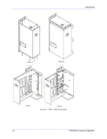
It may be necessary to disassemble the PMAC-Pack to set jumpers or diagnose a system problem. The
following steps serve as a guide to the disassembly of the PMAC-Pack (see Figure 4-1).
1. Uncouple PMAC-Pack from any system connections, unbolt it from the mounting plate, and place the
unit on a clean workbench or table.
2. Remove the eight (8) screws securing the two halves of the PMAC-Pack sheet metal together.
3. Pull the front of PMAC-Pack slightly forward, and rotate it to the left, exposing the interior of the
unit.
4. Remove the three mounting screws securing the PMAC-Lite motion control card as shown. PMAC-
Lite is then free to swivel outward, exposing the component side of the card.
5. Set jumpers as required. (Jumpers E40-47 are replaced by the communications SwitchBank on the
front panel of the PMAC-Pack.)
PMAC-Pack Jumper Setup
Note:
Delta Tau Data Systems, Inc. does not recommend reconfiguring the PMAC-Pack.
All units are shipped in the default configuration. If the default configuration does
not meet your requirements, Delta Tau suggests ordering the PMAC-Pack factory-
configured to your specifications.
Although the vast majority of applications can be accomplished using the default settings of the E-point
jumpers, thereby eliminating the need to open up PMAC-Pack, the E-point jumpers may be used to
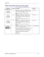
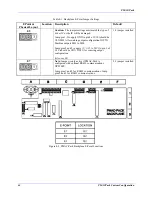
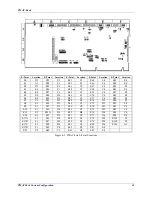
"custom configure" the motion control hardware for specific tasks. Figure 4-2 shows the location of the
backplane E-point jumpers, Figure 4-3 shows the locations of the PMAC-Lite 1.5 card E-point jumpers,
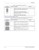
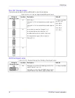
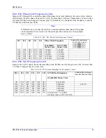
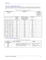
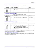
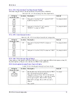
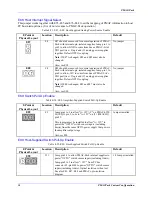
and tables 4-1 through 4-27 provide the information required for customizing the PMAC-Pack backplane
and PMAC-Lite 1.5 card configurations to your specific application.
Содержание PMAC Pack
Страница 10: ...PMAC Pack Table of Contents vii ...
Страница 11: ......
Страница 16: ...PMAC Pack Overview 5 Figure 1 1 PMAC Pack Dimension ...
Страница 27: ...PMAC Pack 16 Overview ...
Страница 47: ...PMAC Pack 36 Getting Started ...
Страница 51: ...PMAC Pack 40 Complying with European Community EMC Requirements ...
Страница 53: ...PMAC Pack 42 PMACPack Custom Configuration Figure 4 1 PMAC Pack Disassembly ...
Страница 70: ...PMAC Pack PMACPack Custom Configuration 59 Figure 4 4 PMAC Pack Assembly ...
Страница 91: ...PMAC Pack 80 Circuit Diagrams Figure 7 2 Basic PMAC Pack Wiring Diagram ...
Страница 92: ...PMAC Pack Circuit Diagrams Figure 7 3 PMAC Pack with Accessory 8D Option 2 Wiring Diagram ...
Страница 93: ...PMAC Pack 82 Circuit Diagrams Figure 7 4 PMAC Pack with Accessory 8D Option 4A Wiring Diagram ...
Страница 94: ...PMAC Pack Circuit Diagrams Figure 7 5 PMAC Pack with Option 9L Wiring Diagram ...
Страница 95: ...PMAC Pack 84 Circuit Diagrams Figure 7 6 PMAC Pack with Accessory 28A Wiring Diagram ...
Страница 96: ...PMAC Pack Circuit Diagrams Figure 7 7 PMAC Pack with Accessory 39 Wiring Diagram ...
Страница 97: ...PMAC Pack 86 Circuit Diagrams ...
Страница 98: ...PMAC Pack Circuit Diagrams 87 ...
Страница 99: ...PMAC Pack 88 Circuit Diagrams ...
Страница 100: ...PMAC Pack Circuit Diagrams 89 ...
Страница 101: ...PMAC Pack 90 Circuit Diagrams ...
Страница 103: ...92 Acc 24E Acc 24EXP Expansion XP Pack Figure 8 1 Expansion Pack Installation ...
Страница 106: ...PMAC Pack Acc 24E Acc 24EXP Expansion XP Pack 95 Figure 8 3 PMAC Pack Assembly ...
Страница 109: ...98 Acc 24E Acc 24EXP Expansion XP Pack ...
Страница 117: ...106 PMACPack Options and Accessories ...


