PMAC-Pack
Getting Started
23
Amplifier Connection (Brush DC Motor or Motor Commutated by the
Amplifier)
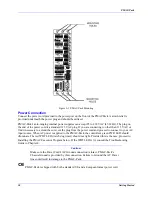
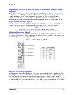
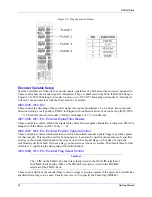
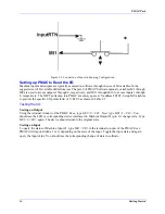
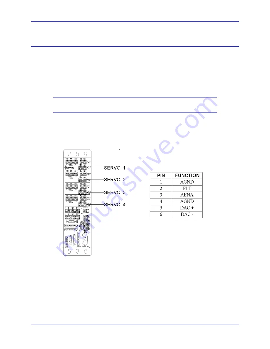
PMAC-Pack interfaces to the system amplifiers through the "SERVO" port. Pinouts are shown in Figure
2-3. Each Axis has a SERVO port which serves to communicate amplifier command signals (Torque or
Velocity), the amplifier enable signal, and amplifier fault signal. If PMAC is not performing the
commutation for the motor, only one analog output channel is required to command the motor. This
output channel can be either single-ended or differential, depending on what the amplifier is expecting.
Single-Ended Command Signal
For a single-ended command using PMAC channel 1, connect DAC1 (pin 5) to the command input on the
amplifier. Connect the amplifier's command signal return line to PMAC's AGND line (pin 4).
Note:
In this setup, leave the DAC1/ pin (pin 6) floating; do not ground it.
Differential Command Signal
For a differential command using PMAC channel 1, connect DAC1 (pin 5) to the plus-command input on
the amplifier. Connect DAC1/ (pin 6) to the minus command input on the amplifier. PMAC's AGND (pin
4) should still be connected to the amplifier common.
Figure 2-3. PMAC-Pack/Amplifier Pinouts
Amplifier Enable Signal (AENA/)
Most amplifiers have an enable/disable input that permits complete shutdown of the amplifier regardless
of the voltage of the command signal. PMAC's AENA/line is meant for this purpose. AENA/ is pin3. This
signal is an open collector output with internal 3.3K pull up resistor to 15Vdc and requires a pull up
resistor. For early tests, you may wish to have this amplifier signal under manual control. The polarity of
the signal is controlled by PMAC-Lite jumper(s) E17. The default is low-true (conducting) enable, which
is the safest polarity because a PMAC shutdown will automatically disable the amplifiers.
Содержание PMAC Pack
Страница 10: ...PMAC Pack Table of Contents vii ...
Страница 11: ......
Страница 16: ...PMAC Pack Overview 5 Figure 1 1 PMAC Pack Dimension ...
Страница 27: ...PMAC Pack 16 Overview ...
Страница 47: ...PMAC Pack 36 Getting Started ...
Страница 51: ...PMAC Pack 40 Complying with European Community EMC Requirements ...
Страница 53: ...PMAC Pack 42 PMACPack Custom Configuration Figure 4 1 PMAC Pack Disassembly ...
Страница 70: ...PMAC Pack PMACPack Custom Configuration 59 Figure 4 4 PMAC Pack Assembly ...
Страница 91: ...PMAC Pack 80 Circuit Diagrams Figure 7 2 Basic PMAC Pack Wiring Diagram ...
Страница 92: ...PMAC Pack Circuit Diagrams Figure 7 3 PMAC Pack with Accessory 8D Option 2 Wiring Diagram ...
Страница 93: ...PMAC Pack 82 Circuit Diagrams Figure 7 4 PMAC Pack with Accessory 8D Option 4A Wiring Diagram ...
Страница 94: ...PMAC Pack Circuit Diagrams Figure 7 5 PMAC Pack with Option 9L Wiring Diagram ...
Страница 95: ...PMAC Pack 84 Circuit Diagrams Figure 7 6 PMAC Pack with Accessory 28A Wiring Diagram ...
Страница 96: ...PMAC Pack Circuit Diagrams Figure 7 7 PMAC Pack with Accessory 39 Wiring Diagram ...
Страница 97: ...PMAC Pack 86 Circuit Diagrams ...
Страница 98: ...PMAC Pack Circuit Diagrams 87 ...
Страница 99: ...PMAC Pack 88 Circuit Diagrams ...
Страница 100: ...PMAC Pack Circuit Diagrams 89 ...
Страница 101: ...PMAC Pack 90 Circuit Diagrams ...
Страница 103: ...92 Acc 24E Acc 24EXP Expansion XP Pack Figure 8 1 Expansion Pack Installation ...
Страница 106: ...PMAC Pack Acc 24E Acc 24EXP Expansion XP Pack 95 Figure 8 3 PMAC Pack Assembly ...
Страница 109: ...98 Acc 24E Acc 24EXP Expansion XP Pack ...
Страница 117: ...106 PMACPack Options and Accessories ...


