PMAC-Pack
Getting Started
27
Motor Variable Setup
A PMAC-Pack can be attached to up to eight motors (with optional expansion Pack), called #1 to #8. A
motor is defined in PMAC by setting up I-variables that tell the I/O addresses of the input and output data
(where to look for the feedback position, and where to send the output command).
The I-variables for motor #1 are in the 100s (I100-I184); for motor #2 in the 200s, and so on, to the 800s
for motor #8. As a shorthand to refer to a particular variable independent of a particular motor, we replace
the hundreds digit with the letter x. For instance, Ix20 refers to I120 for motor 1, or I220 for motor 2, and
so on.
Ix00 Motor Activation
The first thing to do in the software setup of a motor is activate the software algorithms for the motor by
setting Ix00 to 1. For Motor #1, set I100 to 1. (HMFLn).
Ix01 Commutation Enable/Disable
If PMAC is not performing the commutation for the motor, set Ix01 to 0 so that the commutation routines
are disabled and only one analog output is used. In our example using motor 1, set I101 to 0. This is the
default. If commutation is to be used, refer to the PMAC Software Manual's "Getting Started" section for
setup instructions.
Establishing Servo Loop Variables
Several variable values must be established to tell PMAC where to get its servo loop information.
Ix02 DAC Output Address
Ix02 must be set to the register address of the analog output(s) used to command the amplifier. The output
register address for motor #1 is defined using I102. In order to send the motor 1 output command to the
DAC1 outputs we have connected, we must set I102 address $C003 (49155 decimal). This is the default
value. Refer to the PMAC Software Reference Manual, 3A0-602204-363, for a complete address listing
of all DACs.
Ix03 Position-Loop feedback address
Variable Ix03 defines the register to be used for the position-loop servo feedback. Typically, this reads a
processed encoder value from what is known as the encoder conversion table (which you do not need to
worry about yet). To have motor 1 read the processed input from Encoder 1, I103 must be set to 1824
($720). This should be the value preset at the factory.
Ix04 Velocity-Loop (Motor) Feedback Address
It is possible to have separate motor and load feedback encoders (this can allow good control even with
poor coupling). In this case, the sensor on the load is used to close the position loop; it is addressed by
Ix03 (see above). The sensor on the motor is used to close the velocity loop; it is addressed by Ix04. The
vast majority of users will only have one feedback encoder, whether it is on the motor, or on the load. For
these users, Ix04 will be set to the same value as Ix03, addressing the same encoder. If you have just one
feedback encoder (ENC1) for your Motor #1 in our example, make sure I104 is set to 1824, just as I103 is
(this is the default).
Ix25 Flag Address
The +LIM1, -LIM1, and HMFL1 inputs are tied to motor #x by the setup of the Ix25 variable. By setting
this variable \ the card knows where to look for its limit and home flag inputs, (remember that this is
essential to command a move). To use +LIM1, -LIM1, and HMFL1, I125 should be set to ($C000)
49152. This should be the value set at the factory. If you are not using overtravel limit switches and have
not wired the limit pins to ground, set I125 to $2C000. Refer to 3A0-602204-363 for further details.
Содержание PMAC Pack
Страница 10: ...PMAC Pack Table of Contents vii ...
Страница 11: ......
Страница 16: ...PMAC Pack Overview 5 Figure 1 1 PMAC Pack Dimension ...
Страница 27: ...PMAC Pack 16 Overview ...
Страница 47: ...PMAC Pack 36 Getting Started ...
Страница 51: ...PMAC Pack 40 Complying with European Community EMC Requirements ...
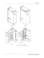
Страница 53: ...PMAC Pack 42 PMACPack Custom Configuration Figure 4 1 PMAC Pack Disassembly ...
Страница 70: ...PMAC Pack PMACPack Custom Configuration 59 Figure 4 4 PMAC Pack Assembly ...
Страница 91: ...PMAC Pack 80 Circuit Diagrams Figure 7 2 Basic PMAC Pack Wiring Diagram ...
Страница 92: ...PMAC Pack Circuit Diagrams Figure 7 3 PMAC Pack with Accessory 8D Option 2 Wiring Diagram ...
Страница 93: ...PMAC Pack 82 Circuit Diagrams Figure 7 4 PMAC Pack with Accessory 8D Option 4A Wiring Diagram ...
Страница 94: ...PMAC Pack Circuit Diagrams Figure 7 5 PMAC Pack with Option 9L Wiring Diagram ...
Страница 95: ...PMAC Pack 84 Circuit Diagrams Figure 7 6 PMAC Pack with Accessory 28A Wiring Diagram ...
Страница 96: ...PMAC Pack Circuit Diagrams Figure 7 7 PMAC Pack with Accessory 39 Wiring Diagram ...
Страница 97: ...PMAC Pack 86 Circuit Diagrams ...
Страница 98: ...PMAC Pack Circuit Diagrams 87 ...
Страница 99: ...PMAC Pack 88 Circuit Diagrams ...
Страница 100: ...PMAC Pack Circuit Diagrams 89 ...
Страница 101: ...PMAC Pack 90 Circuit Diagrams ...
Страница 103: ...92 Acc 24E Acc 24EXP Expansion XP Pack Figure 8 1 Expansion Pack Installation ...
Страница 106: ...PMAC Pack Acc 24E Acc 24EXP Expansion XP Pack 95 Figure 8 3 PMAC Pack Assembly ...
Страница 109: ...98 Acc 24E Acc 24EXP Expansion XP Pack ...
Страница 117: ...106 PMACPack Options and Accessories ...


