PMAC-Pack
22
Getting
Started
Incremental Encoder Connection
Warning:
Remove power from PMAC-Pack before connecting encoders
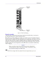
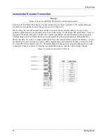
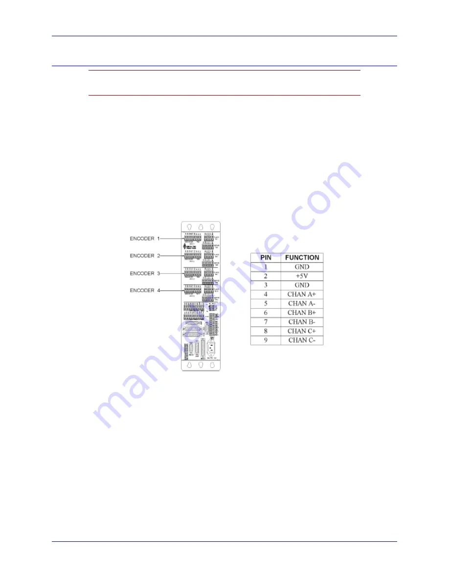
Each axis of the PMAC-Pack has an encoder connection port. It also provides a +5V output and logic
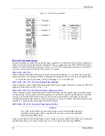
ground for powering the encoder. Pinouts are shown in Figure 2-2.
When wiring, the encoder number does not have to match the axis number unless you want to use
position capture features, but it usually does. Later in the setup, we will insure that each PMAC "Axis" is
mapped to the desired Encoder. Connect the A and B (quadrature) encoder channels to the appropriate
terminal block pins. The PMAC-Pack is setup by default for either single-ended or differential Line-
Driver encoders. If you have a single ended signal, leave the complementary signal pins floating -- do not
ground them. If you are using an encoder with complementary open collector outputs, you must set E24-
27 on the PMAC-lite board to pins 2-3. The third channel (index pulse) is optional, although if you wish
to precisely home your motor, it is highly recommended to use an encoder with an index channel.
Figure 2-2. Encoder Connection Port Pinouts
Содержание PMAC Pack
Страница 10: ...PMAC Pack Table of Contents vii ...
Страница 11: ......
Страница 16: ...PMAC Pack Overview 5 Figure 1 1 PMAC Pack Dimension ...
Страница 27: ...PMAC Pack 16 Overview ...
Страница 47: ...PMAC Pack 36 Getting Started ...
Страница 51: ...PMAC Pack 40 Complying with European Community EMC Requirements ...
Страница 53: ...PMAC Pack 42 PMACPack Custom Configuration Figure 4 1 PMAC Pack Disassembly ...
Страница 70: ...PMAC Pack PMACPack Custom Configuration 59 Figure 4 4 PMAC Pack Assembly ...
Страница 91: ...PMAC Pack 80 Circuit Diagrams Figure 7 2 Basic PMAC Pack Wiring Diagram ...
Страница 92: ...PMAC Pack Circuit Diagrams Figure 7 3 PMAC Pack with Accessory 8D Option 2 Wiring Diagram ...
Страница 93: ...PMAC Pack 82 Circuit Diagrams Figure 7 4 PMAC Pack with Accessory 8D Option 4A Wiring Diagram ...
Страница 94: ...PMAC Pack Circuit Diagrams Figure 7 5 PMAC Pack with Option 9L Wiring Diagram ...
Страница 95: ...PMAC Pack 84 Circuit Diagrams Figure 7 6 PMAC Pack with Accessory 28A Wiring Diagram ...
Страница 96: ...PMAC Pack Circuit Diagrams Figure 7 7 PMAC Pack with Accessory 39 Wiring Diagram ...
Страница 97: ...PMAC Pack 86 Circuit Diagrams ...
Страница 98: ...PMAC Pack Circuit Diagrams 87 ...
Страница 99: ...PMAC Pack 88 Circuit Diagrams ...
Страница 100: ...PMAC Pack Circuit Diagrams 89 ...
Страница 101: ...PMAC Pack 90 Circuit Diagrams ...
Страница 103: ...92 Acc 24E Acc 24EXP Expansion XP Pack Figure 8 1 Expansion Pack Installation ...
Страница 106: ...PMAC Pack Acc 24E Acc 24EXP Expansion XP Pack 95 Figure 8 3 PMAC Pack Assembly ...
Страница 109: ...98 Acc 24E Acc 24EXP Expansion XP Pack ...
Страница 117: ...106 PMACPack Options and Accessories ...


