PMAC-Pack
Getting Started
33
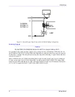
Figure 2-7. General Purpose Output Connected in the Optional Sourcing Configuration
Input Source/Sink Control
The method of interconnection to the general purpose inputs (JOPT INPUTS) determines the
sinking/sourcing configuration of the eight inputs. In the sinking configuration, the inputs are biased to
+V for the “OFF” state, and must be pulled low for the “ON” state. In the sourcing configuration, the
inputs are biased to ground for the “OFF” state, and must be pulled high for the “ON” state. In either case,
a high voltage is interpreted as a ‘0’ by the PMAC software, and a low voltage is interpreted as a ‘1’.
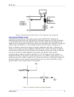
Figure 2-8 illustrates connection of an input in a Sinking configuration and Figure 2-9 illustrates the
connection of an input in sourcing configuration. When the switch is closed, current flows through the
switch and into the PMAC-Pack’s opto-isolator to the Limit Return which is tied to common. When the
switch is closed, current is pulled through the opto-isolator in the PMAC-PACK to ground.
The general purpose inputs are capable of operation at 12 to 24 DC voltage levels. If you desire to
maintain full isoV should be a separate voltage source. It is possible to operate using the +12V
available on pin 2 of each “Flags” connector as the voltage source. However, it should be noted that this
defeats the isolation circuitry causing the general input circuitry to be referenced to PMAC’s analog
ground (AGND) which is typically shared by the amplifier.
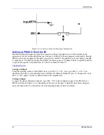
Figure 2-8. Connection of Input in Sinking Configuration
Содержание PMAC Pack
Страница 10: ...PMAC Pack Table of Contents vii ...
Страница 11: ......
Страница 16: ...PMAC Pack Overview 5 Figure 1 1 PMAC Pack Dimension ...
Страница 27: ...PMAC Pack 16 Overview ...
Страница 47: ...PMAC Pack 36 Getting Started ...
Страница 51: ...PMAC Pack 40 Complying with European Community EMC Requirements ...
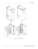
Страница 53: ...PMAC Pack 42 PMACPack Custom Configuration Figure 4 1 PMAC Pack Disassembly ...
Страница 70: ...PMAC Pack PMACPack Custom Configuration 59 Figure 4 4 PMAC Pack Assembly ...
Страница 91: ...PMAC Pack 80 Circuit Diagrams Figure 7 2 Basic PMAC Pack Wiring Diagram ...
Страница 92: ...PMAC Pack Circuit Diagrams Figure 7 3 PMAC Pack with Accessory 8D Option 2 Wiring Diagram ...
Страница 93: ...PMAC Pack 82 Circuit Diagrams Figure 7 4 PMAC Pack with Accessory 8D Option 4A Wiring Diagram ...
Страница 94: ...PMAC Pack Circuit Diagrams Figure 7 5 PMAC Pack with Option 9L Wiring Diagram ...
Страница 95: ...PMAC Pack 84 Circuit Diagrams Figure 7 6 PMAC Pack with Accessory 28A Wiring Diagram ...
Страница 96: ...PMAC Pack Circuit Diagrams Figure 7 7 PMAC Pack with Accessory 39 Wiring Diagram ...
Страница 97: ...PMAC Pack 86 Circuit Diagrams ...
Страница 98: ...PMAC Pack Circuit Diagrams 87 ...
Страница 99: ...PMAC Pack 88 Circuit Diagrams ...
Страница 100: ...PMAC Pack Circuit Diagrams 89 ...
Страница 101: ...PMAC Pack 90 Circuit Diagrams ...
Страница 103: ...92 Acc 24E Acc 24EXP Expansion XP Pack Figure 8 1 Expansion Pack Installation ...
Страница 106: ...PMAC Pack Acc 24E Acc 24EXP Expansion XP Pack 95 Figure 8 3 PMAC Pack Assembly ...
Страница 109: ...98 Acc 24E Acc 24EXP Expansion XP Pack ...
Страница 117: ...106 PMACPack Options and Accessories ...

