PMAC-Pack
28
Getting
Started
Ix69 DAC Output Range
Check the voltage range of the output command by looking at I169. This is the magnitude of the
maximum value that can be written to the DAC, whose full range is -32,768 to +32,767 (16 bits for
)
10V). The default value of I169 is 20,480, which is about
)
6.25V. If your amplifier is expecting
=
)
10V
and you wish to use the full range, set I169 to 32,767. If your amplifier is expecting a differential signal
with up to
)
10V between the lines (each line is
)
5V), set I169 to 16,384 or less.
Verifying Position Feedback
Now we should be able to start checking on some basic motor functions. First we will try to read motor
position. With the Executive program in terminal mode, type
#1<CR>
to address motor 1. Next, type
P<CR>
, and PMAC should return a position value to the terminal screen. Turn the motor shaft by hand
and type
P<CR>
again. The reported position should have changed. Alternately, use the F7 position
reporting window of the PMAC Executive program, which automatically polls position repeatedly.
Repeat this as often as you like to satisfy yourself that the position counting is working properly in both
directions. If the position count does not change, reference the Troubleshooting Guide in Chapter 4.
Changing Position Direction
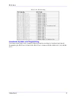
If you are getting position feedback, but want to change the positive and negative directions, use I900 (for
ENC 1) to change the direction sense (or exchange the Channel A and Channel B inputs). For example, if
I900 is 7, changing it to 3 will change the direction sense. If the motor does not move or if you encounter
a polarity mismatch, refer to the Troubleshooting Guide in Chapter 4.
Testing the Command Output and Polarity
Next, we will check the command outputs and whether the output polarity matches the feedback polarity.
To do this we will need to provide power to our amplifier. First, have PMAC disable its own outputs for
the motor by typing
K<CR>
(kill). Make sure that the motor has no load at this point so that uncontrolled
motion cannot damage anything. Now provide power to the amplifier.
If PMAC is not doing the commutation for a motor, we must make sure that the servo feedback and
output polarities match. We do this by giving the motor an open-loop output command and seeing which
way the position counts. Type
O10<CR>
(open-loop output 10%). The position counter should count up.
If it counts down, you have a polarity mismatch. Now type
O-10<CR>
. The position counter should
count down. If it counts up, you have a polarity mismatch. If the counter does not count in opposite
directions for the two tests, you have an encoder and/or amplifier problem.
Verify Overtravel Limit Polarity.
Make sure as you verify the direction sense of the motor that you have your hardware position limit
switches wired into the proper inputs. That is, the limit switch on the positive (counting up) end of travel
must be wired into the POSLIM input, and the switch on the negative end must be wired into the
NEGLIM input. If these are reversed, your hardware limit functions will not work.
Manually trip the limit. Using the PMAC Exec, you can monitor "Motor Status". When the +EOT Limit
is tripped, the
positive
limit indicator should illuminate. When the -EOT Limit is tripped, the
negative
limit indicator should illuminate.
Содержание PMAC Pack
Страница 10: ...PMAC Pack Table of Contents vii ...
Страница 11: ......
Страница 16: ...PMAC Pack Overview 5 Figure 1 1 PMAC Pack Dimension ...
Страница 27: ...PMAC Pack 16 Overview ...
Страница 47: ...PMAC Pack 36 Getting Started ...
Страница 51: ...PMAC Pack 40 Complying with European Community EMC Requirements ...
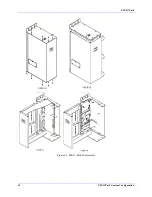
Страница 53: ...PMAC Pack 42 PMACPack Custom Configuration Figure 4 1 PMAC Pack Disassembly ...
Страница 70: ...PMAC Pack PMACPack Custom Configuration 59 Figure 4 4 PMAC Pack Assembly ...
Страница 91: ...PMAC Pack 80 Circuit Diagrams Figure 7 2 Basic PMAC Pack Wiring Diagram ...
Страница 92: ...PMAC Pack Circuit Diagrams Figure 7 3 PMAC Pack with Accessory 8D Option 2 Wiring Diagram ...
Страница 93: ...PMAC Pack 82 Circuit Diagrams Figure 7 4 PMAC Pack with Accessory 8D Option 4A Wiring Diagram ...
Страница 94: ...PMAC Pack Circuit Diagrams Figure 7 5 PMAC Pack with Option 9L Wiring Diagram ...
Страница 95: ...PMAC Pack 84 Circuit Diagrams Figure 7 6 PMAC Pack with Accessory 28A Wiring Diagram ...
Страница 96: ...PMAC Pack Circuit Diagrams Figure 7 7 PMAC Pack with Accessory 39 Wiring Diagram ...
Страница 97: ...PMAC Pack 86 Circuit Diagrams ...
Страница 98: ...PMAC Pack Circuit Diagrams 87 ...
Страница 99: ...PMAC Pack 88 Circuit Diagrams ...
Страница 100: ...PMAC Pack Circuit Diagrams 89 ...
Страница 101: ...PMAC Pack 90 Circuit Diagrams ...
Страница 103: ...92 Acc 24E Acc 24EXP Expansion XP Pack Figure 8 1 Expansion Pack Installation ...
Страница 106: ...PMAC Pack Acc 24E Acc 24EXP Expansion XP Pack 95 Figure 8 3 PMAC Pack Assembly ...
Страница 109: ...98 Acc 24E Acc 24EXP Expansion XP Pack ...
Страница 117: ...106 PMACPack Options and Accessories ...


