PMAC-Pack
38
Complying with European Community EMC Requirements
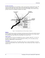
D-Type Connectors
D-type connectors must have a metal housing to ensure a proper ground is established between the cable
connector and the PMAC-Pack connector. Drain wires and grounding pigtails must have a grommet
attached. This grommet is then secured under one of the connector mounting screws to ensure a proper
ground between the cable shielding and the PMAC-Pack chassis.
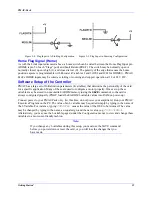
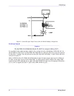
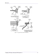
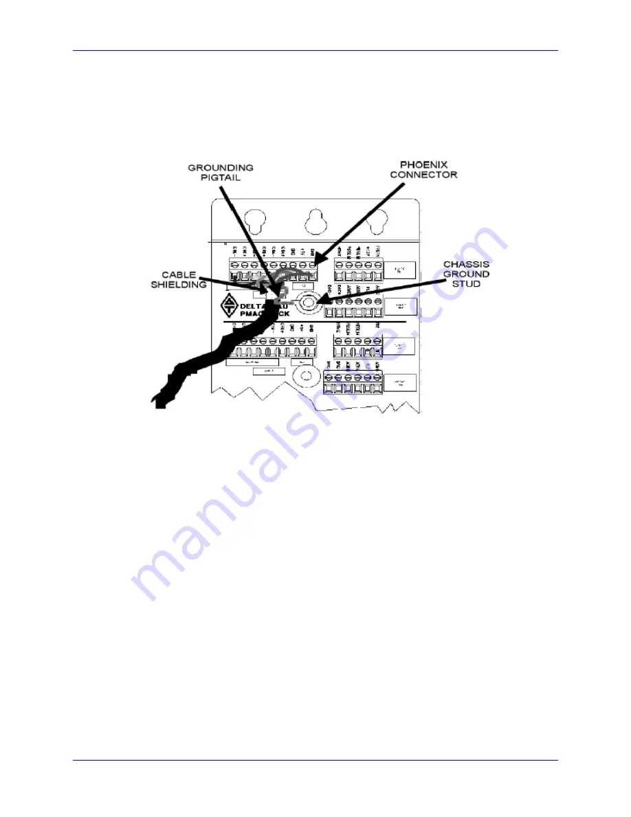
Figure 3-1. Grounding Procedures for Phoenix Plug-In Connectors
Cables
The most common types of cable used for PMAC-Pack installation are dedicated cable with foil wrap and
braided shielding, twisted shielded cable, flat-shielded cable, and flat cable in a twist with shield. Figure
3-2 demonstrates the proper installation and grounding for these types of cable.
Signal Cables
The exposed portion of signal cable shielding must be kept to a minimum, nominally 10 to 12 mm. If a
backshell is being used, Delta Tau recommends pulling the shielding over the outer sheath, passing it
through the backshell clamp, and then clamping it.
Flat Cables
All flat (ribbon) cabling must have 360
o
shielding with a drain wire. Ensure the shielding is in complete
contact with the metal portion of the connector and crimp it with a termination ring or tape it in place with
conductive tape.
Содержание PMAC Pack
Страница 10: ...PMAC Pack Table of Contents vii ...
Страница 11: ......
Страница 16: ...PMAC Pack Overview 5 Figure 1 1 PMAC Pack Dimension ...
Страница 27: ...PMAC Pack 16 Overview ...
Страница 47: ...PMAC Pack 36 Getting Started ...
Страница 51: ...PMAC Pack 40 Complying with European Community EMC Requirements ...
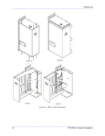
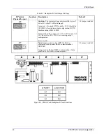
Страница 53: ...PMAC Pack 42 PMACPack Custom Configuration Figure 4 1 PMAC Pack Disassembly ...
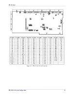
Страница 70: ...PMAC Pack PMACPack Custom Configuration 59 Figure 4 4 PMAC Pack Assembly ...
Страница 91: ...PMAC Pack 80 Circuit Diagrams Figure 7 2 Basic PMAC Pack Wiring Diagram ...
Страница 92: ...PMAC Pack Circuit Diagrams Figure 7 3 PMAC Pack with Accessory 8D Option 2 Wiring Diagram ...
Страница 93: ...PMAC Pack 82 Circuit Diagrams Figure 7 4 PMAC Pack with Accessory 8D Option 4A Wiring Diagram ...
Страница 94: ...PMAC Pack Circuit Diagrams Figure 7 5 PMAC Pack with Option 9L Wiring Diagram ...
Страница 95: ...PMAC Pack 84 Circuit Diagrams Figure 7 6 PMAC Pack with Accessory 28A Wiring Diagram ...
Страница 96: ...PMAC Pack Circuit Diagrams Figure 7 7 PMAC Pack with Accessory 39 Wiring Diagram ...
Страница 97: ...PMAC Pack 86 Circuit Diagrams ...
Страница 98: ...PMAC Pack Circuit Diagrams 87 ...
Страница 99: ...PMAC Pack 88 Circuit Diagrams ...
Страница 100: ...PMAC Pack Circuit Diagrams 89 ...
Страница 101: ...PMAC Pack 90 Circuit Diagrams ...
Страница 103: ...92 Acc 24E Acc 24EXP Expansion XP Pack Figure 8 1 Expansion Pack Installation ...
Страница 106: ...PMAC Pack Acc 24E Acc 24EXP Expansion XP Pack 95 Figure 8 3 PMAC Pack Assembly ...
Страница 109: ...98 Acc 24E Acc 24EXP Expansion XP Pack ...
Страница 117: ...106 PMACPack Options and Accessories ...

