PMAC-Pack
PMACPack Options and Accessories
99
PMAC-PACK OPTIONS AND ACCESSORIES
PMAC-Pack Internal Options & Accessories
ACC8D-Option 2PP: Stepper Drive Interface
This option provides 4 voltage-to-frequency (V/F) converters for commanding stepper motor drive
systems. These convert PMAC’s analog output for each channel to a pulse output. The pulse output can
be jumpered back to PMAC’s encoder input for the motor if the system is to be run open loop, or an
actual encoder can be used for true closed-loop servo control. The maximum frequency is selectable from
10KHz to 2MHz. Both servo and stepper axes can be used together allowing combinations of both motor
types, up to a total of 4 motors, to be controlled.
This option is a small, separate board which is internally mounted and connected within the PMAC-Pack
when the option is ordered. Interface to the stepper amp is via the ] TBOUT connector. Expanded
documentation for ACC8D-OPT2PP is currently under development. At present, request the ACC8D-
OPT2 manual for further information.
ACC8D-Option 4PP: Hydraulic Valve Driver
Provides four low-power current-loop (transconductance) amplifier circuits for driving hydraulic valves
or very small DC motors. Each of the linear amplifier circuits is rated at 40W continuous output. This
option is a small, separate, internally mounted, PC Board with a built-in heat sink and fan. One of three
maximum current settings can be jumper selected: 100, 200, or 2000 mA. A voltage mode provides a
proportional voltage output, with a peak current of 3 amps. Expanded documentation for PMAC-Pack
ACC8D-OPT4PP is under development. At present, request the ACC8D-OPT4 manual for further
information.
ACC8D-Option 4APP: PWM Amplifier
Provides four low-power current-loop (transconductance) amplifier circuits for driving proportional
hydraulic valve actuators or small to medium size DC motors. Each of the pulse-width modulated
(PWM)amplifier circuits is rated at 150W continuous output (250W-1 second intermittent). PWM
operation is at 30KHz and is short-circuit protected. Shunt-regulation provides over-voltage protection.
Output can range from 15 - 48 volts at 3A continuous, and 5 amps peak per channel. This option is a
small, separate, internally mounted, option board with a built-in heat sink and fan. Expanded
documentation for PMACPack ACC8D-OPT4APP is under development. At present, request the
ACC8D-OPT4A manual for further information.
Option 9LPP: Optional RS422 Interface
Integrated RS-422 serial interface adapter board for PMAC-Lite. Replaces standard RS-232 interface.
DB25 pin connector serves as serial port link. DB9 connector is rendered inoperative. Expanded
documentation for PMAC-Pack OPT 9LPP is under development. At present, request the Opt 9L manual
for further information.
Accessory 24PP: PMAC-Pack Expansion Pack
Provides 4 additional encoder channels and 4 additional DAC outputs which may be used to expand
PMAC-Packs control abilities to 8 non-commutated axes or 4 commutated axes. For further information,
refer to Chapter 7.
Accessory 28APP: A/D Conversion Board
PMAC-Pack Accessory-28APP Analog-to-Digital Conversion board has four channels of high-speed (45
usec), high resolution (13 bit effective) analog input in the
)
10V range. It is a small, internally mounted
option board that connects to PMAC with a provided flat cable. These inputs can be used for servo
position feedback, as from an LVDT or potentiometer, or for general purpose use; for instance to monitor
process variables such as pressure or tension, to allow analog speed control, or to monitor motor currents.
Содержание PMAC Pack
Страница 10: ...PMAC Pack Table of Contents vii ...
Страница 11: ......
Страница 16: ...PMAC Pack Overview 5 Figure 1 1 PMAC Pack Dimension ...
Страница 27: ...PMAC Pack 16 Overview ...
Страница 47: ...PMAC Pack 36 Getting Started ...
Страница 51: ...PMAC Pack 40 Complying with European Community EMC Requirements ...
Страница 53: ...PMAC Pack 42 PMACPack Custom Configuration Figure 4 1 PMAC Pack Disassembly ...
Страница 70: ...PMAC Pack PMACPack Custom Configuration 59 Figure 4 4 PMAC Pack Assembly ...
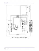
Страница 91: ...PMAC Pack 80 Circuit Diagrams Figure 7 2 Basic PMAC Pack Wiring Diagram ...
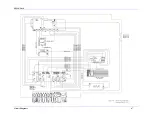
Страница 92: ...PMAC Pack Circuit Diagrams Figure 7 3 PMAC Pack with Accessory 8D Option 2 Wiring Diagram ...
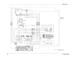
Страница 93: ...PMAC Pack 82 Circuit Diagrams Figure 7 4 PMAC Pack with Accessory 8D Option 4A Wiring Diagram ...
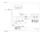
Страница 94: ...PMAC Pack Circuit Diagrams Figure 7 5 PMAC Pack with Option 9L Wiring Diagram ...
Страница 95: ...PMAC Pack 84 Circuit Diagrams Figure 7 6 PMAC Pack with Accessory 28A Wiring Diagram ...
Страница 96: ...PMAC Pack Circuit Diagrams Figure 7 7 PMAC Pack with Accessory 39 Wiring Diagram ...
Страница 97: ...PMAC Pack 86 Circuit Diagrams ...
Страница 98: ...PMAC Pack Circuit Diagrams 87 ...
Страница 99: ...PMAC Pack 88 Circuit Diagrams ...
Страница 100: ...PMAC Pack Circuit Diagrams 89 ...
Страница 101: ...PMAC Pack 90 Circuit Diagrams ...
Страница 103: ...92 Acc 24E Acc 24EXP Expansion XP Pack Figure 8 1 Expansion Pack Installation ...
Страница 106: ...PMAC Pack Acc 24E Acc 24EXP Expansion XP Pack 95 Figure 8 3 PMAC Pack Assembly ...
Страница 109: ...98 Acc 24E Acc 24EXP Expansion XP Pack ...
Страница 117: ...106 PMACPack Options and Accessories ...


