PMAC-Pack
Getting Started
31
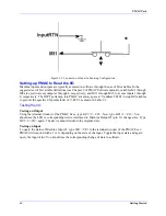
Setting up a Homing Search Move
To do a homing search move, first check your position-capture I-variables (I902 and I903 in our
example). Make sure they are set up to capture the position where you want your home position. With a
bare motor, we can probably only use the third channel of the encoder. Set I902 to 1 to force a capture on
the rising edge of the third channel.
Next, set your homing speed with I123 (in units of counts/millisecond). Changing the sign of I123
changes the direction of the homing move. Homing accel/decel is controlled by I120 and I121 (which also
affect jog moves). Now you can command a homing move with the
HM
command, and the motor will
move as specified until the proper signal edge(s) is found, then decelerate to a stop and come back to the
position of the trigger, plus or minus an offset amount determined by I126.
Connecting Machine I/O
Caution:
PMAC-Pack is designed such that you never need to change jumpers on the
PMAC card to configure I/O as sinking or sourcing. Jumpers E1, E2 , and E7 on
the PMAC-Lite Card should never be changed from pins 1-2.
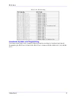
PMAC-Pack’s JOPT INPUT and JOPT OUTPUT connectors provide eight general-purpose digital inputs
and eight general purpose digital outputs. Each I/O point is opto-isolated and designed for direct
connection to 12 to 24V I/O.
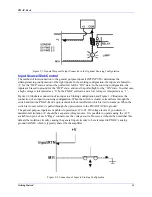
For basic familiarization with PMAC-Pack’s machine I/O, you can use a 2- position switch and an LED,
moving on to actual I/O connection when satisfied that you can control their logic.
General Purpose Digital Outputs
Sinking Outputs (Standard)
Caution:
As default, E4 and E5 are both set to pins 1 and 2. Having PMAC-Pack Backplane
Jumpers E4 and E5 set wrong can damage the IC!
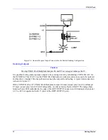
PMAC-Pack is shipped as standard with a ULN2803A sinking (open collector) output IC for the eight
outputs. These outputs can sink up to 100 mA, and utilize internal 3.3Kohm pull up resistors to go high. A
typical interface is shown in Figure 2- 6.
The user can provide a high side voltage (+12 to +24V) into +V (pin 2) of the JOPTO OUT connector,
and allow this to pull up the outputs by connecting pins 1 and 2 of the PMAC-Pack Backplane Jumper
E4. Backplane jumper E5 must also connect pins 1 and 2 for ULN2803A sinking output.
Содержание PMAC Pack
Страница 10: ...PMAC Pack Table of Contents vii ...
Страница 11: ......
Страница 16: ...PMAC Pack Overview 5 Figure 1 1 PMAC Pack Dimension ...
Страница 27: ...PMAC Pack 16 Overview ...
Страница 47: ...PMAC Pack 36 Getting Started ...
Страница 51: ...PMAC Pack 40 Complying with European Community EMC Requirements ...
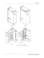
Страница 53: ...PMAC Pack 42 PMACPack Custom Configuration Figure 4 1 PMAC Pack Disassembly ...
Страница 70: ...PMAC Pack PMACPack Custom Configuration 59 Figure 4 4 PMAC Pack Assembly ...
Страница 91: ...PMAC Pack 80 Circuit Diagrams Figure 7 2 Basic PMAC Pack Wiring Diagram ...
Страница 92: ...PMAC Pack Circuit Diagrams Figure 7 3 PMAC Pack with Accessory 8D Option 2 Wiring Diagram ...
Страница 93: ...PMAC Pack 82 Circuit Diagrams Figure 7 4 PMAC Pack with Accessory 8D Option 4A Wiring Diagram ...
Страница 94: ...PMAC Pack Circuit Diagrams Figure 7 5 PMAC Pack with Option 9L Wiring Diagram ...
Страница 95: ...PMAC Pack 84 Circuit Diagrams Figure 7 6 PMAC Pack with Accessory 28A Wiring Diagram ...
Страница 96: ...PMAC Pack Circuit Diagrams Figure 7 7 PMAC Pack with Accessory 39 Wiring Diagram ...
Страница 97: ...PMAC Pack 86 Circuit Diagrams ...
Страница 98: ...PMAC Pack Circuit Diagrams 87 ...
Страница 99: ...PMAC Pack 88 Circuit Diagrams ...
Страница 100: ...PMAC Pack Circuit Diagrams 89 ...
Страница 101: ...PMAC Pack 90 Circuit Diagrams ...
Страница 103: ...92 Acc 24E Acc 24EXP Expansion XP Pack Figure 8 1 Expansion Pack Installation ...
Страница 106: ...PMAC Pack Acc 24E Acc 24EXP Expansion XP Pack 95 Figure 8 3 PMAC Pack Assembly ...
Страница 109: ...98 Acc 24E Acc 24EXP Expansion XP Pack ...
Страница 117: ...106 PMACPack Options and Accessories ...


