PMAC-Pack
Getting Started
25
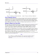
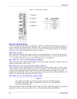
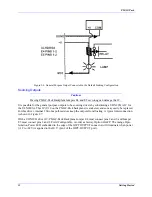
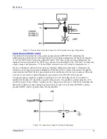
Figure 2-4. Flag Input in A Sinking Configuration Figure 2-5. Flag Input in Sourcing Configuration
Home Flag Signal (Home)
As with the Limit inputs discussed above, a home switch can be wired between the Home Flag Input pin
(HOME is pin 5 of each “Flags” port) and Fault Return (FRET). The switch may be normally open or
normally closed; open is high (1), and closed is low (0). The polarity of the edge that causes the home
position capture is programmable with Encoder I-Variables 2 and 3 (I902 and I903 for HOME1). PMAC-
Pack’s HOME inputs may be wired as sinking or sourcing and support operation at 12 or 24 V DC.
Software Setup of the Controller
PMAC has a large set of Initialization parameters (I-variables) that determine the personality of the card
for a specific application. Many of these are used to configure a motor properly. Once set up, these
variables may be stored in nonvolatile EAROM memory (using the
SAVE
command) so the card is
always configured properly (PMAC loads the EAROM I-variable values into RAM on power-up).
Connect power to your PMAC-Pack only. (At this time, do not power your amplifiers.) Run your PMAC
Executive Program on the PC. The value of an I-variable may be queried simply by typing in the name of
the I-Variable. For instance, typing
I900<CR>
causes the value of the I900 to be returned. The value
may be changed by typing in the name, an equals sign, and the new value (e.g.
I900=3<CR>
).
Alternatively, you may use the I-variable pages (under the
Configuration
menu) to view and change these
variables in a more user-friendly fashion.
Note:
If you change any I-variables during this setup, you must use the SAVE command
before you power down or reset the card, or you will lose the changes that you
have made.
Содержание PMAC Pack
Страница 10: ...PMAC Pack Table of Contents vii ...
Страница 11: ......
Страница 16: ...PMAC Pack Overview 5 Figure 1 1 PMAC Pack Dimension ...
Страница 27: ...PMAC Pack 16 Overview ...
Страница 47: ...PMAC Pack 36 Getting Started ...
Страница 51: ...PMAC Pack 40 Complying with European Community EMC Requirements ...
Страница 53: ...PMAC Pack 42 PMACPack Custom Configuration Figure 4 1 PMAC Pack Disassembly ...
Страница 70: ...PMAC Pack PMACPack Custom Configuration 59 Figure 4 4 PMAC Pack Assembly ...
Страница 91: ...PMAC Pack 80 Circuit Diagrams Figure 7 2 Basic PMAC Pack Wiring Diagram ...
Страница 92: ...PMAC Pack Circuit Diagrams Figure 7 3 PMAC Pack with Accessory 8D Option 2 Wiring Diagram ...
Страница 93: ...PMAC Pack 82 Circuit Diagrams Figure 7 4 PMAC Pack with Accessory 8D Option 4A Wiring Diagram ...
Страница 94: ...PMAC Pack Circuit Diagrams Figure 7 5 PMAC Pack with Option 9L Wiring Diagram ...
Страница 95: ...PMAC Pack 84 Circuit Diagrams Figure 7 6 PMAC Pack with Accessory 28A Wiring Diagram ...
Страница 96: ...PMAC Pack Circuit Diagrams Figure 7 7 PMAC Pack with Accessory 39 Wiring Diagram ...
Страница 97: ...PMAC Pack 86 Circuit Diagrams ...
Страница 98: ...PMAC Pack Circuit Diagrams 87 ...
Страница 99: ...PMAC Pack 88 Circuit Diagrams ...
Страница 100: ...PMAC Pack Circuit Diagrams 89 ...
Страница 101: ...PMAC Pack 90 Circuit Diagrams ...
Страница 103: ...92 Acc 24E Acc 24EXP Expansion XP Pack Figure 8 1 Expansion Pack Installation ...
Страница 106: ...PMAC Pack Acc 24E Acc 24EXP Expansion XP Pack 95 Figure 8 3 PMAC Pack Assembly ...
Страница 109: ...98 Acc 24E Acc 24EXP Expansion XP Pack ...
Страница 117: ...106 PMACPack Options and Accessories ...


