DESIGNER’S HANDBOOK 4189350049C EN
Page 66 of 206
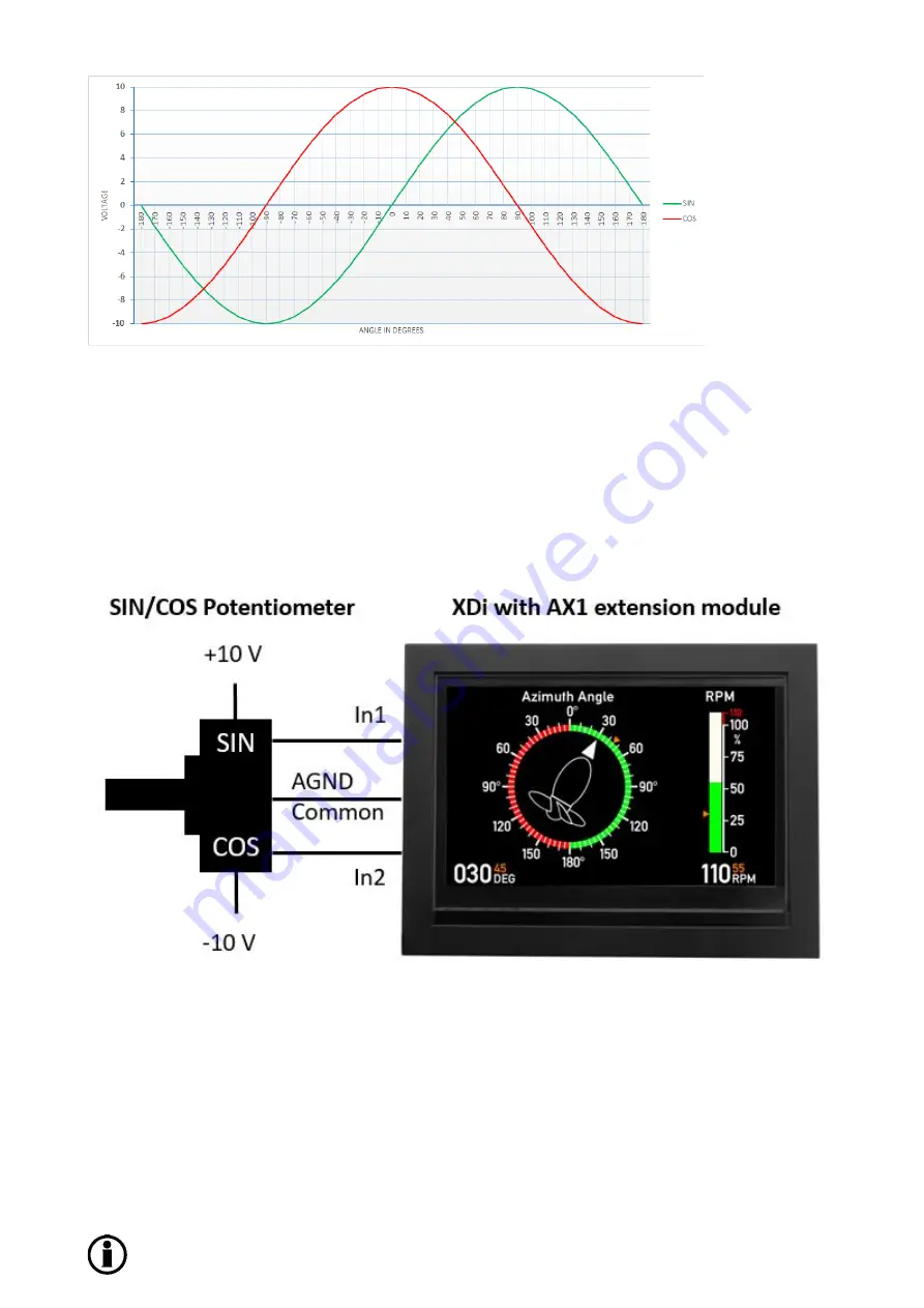
In the VS profile, the sin/cos max input voltage must not exceed the selected measuring range. If for example the
voltage max. swing is +/-10V (as in above figure) then the selected voltage range for the dual inputs are set to +/-
15V to make sure that the voltage always is within then range. Sel/-30V will also work fine but may reduce
the accuracy slightly (but in most cases not noticeable).
Due to the nature of the sin/cos signals, the XDi can compensate for variations in the supply voltage to the
potentiometer at least up to the max input voltage limit and down to a few volt. To obtain a good resolution and not
risking running the input circuit into saturation, the selected input range should be the nearest higher range.
Example: In the DEIF standard library for azimuth thruster indication, it is possible to select a VS for sin/cos
potentiometer input. This input pair has a predefined potentiometer supply voltage of +/-10 V, but this indicator will
also work fine with any potentiometer supply b/- 6 V and +/-15 V.
The high voltage input resistance of the AX1 module is 112
kΩ, and it is therefore possible to connect the sin and
cos potentiometer wiper directly to the input, without any pre-amplifier.
The sin/cos potentiometer resistance should be as low as possible; this will minimise the influence of the internal
resistance in the AX1 module.
It is recommended to use a SIN/COS potentiometer in the range of 500
Ω to 5 kΩ.
A sin/cos input pair cannot be changed to single input via the XDi menu or vice versa.


