DESIGNER’S HANDBOOK 4189350049C EN
Page 77 of 206
To eliminate flicker, it may be necessary to increase the raw data filter value via the XDi user menu by entering the
dimmer source setup menu. Alternatively, the capacity C can be increased.
The raw data filter can be set between 0 and 100 (0 is OFF). The filter value indicates the number of samples used
for averaging.
In the example above, a change of Raw data filter value from 10 to 100 will increase the averaging time from 1 to
10 seconds (100 samples of 100 ms).
Dimmer error handling
In DEIF standard libraries, the default dimmer settings and behaviour are predefined in the available selection of
Product Profiles (PPs). Select a PP that best match the dimmer needs and make necessary parameter adjustments
to match the installation using the XDi user menu.
When a customised library is made, it should be considered how the dimmer must behave when for example the
potentiometer wiper loses its connection, or the dimmer supply fails. If the dimmer input is a traditional input where
0 V equals minimum backlight (0 %) and 24 V is maximum backlight (100 %), then a lost dimmer input will result in
a nearly black display.
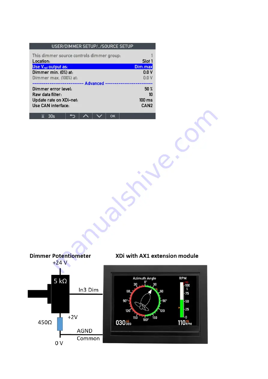
It is possible to reverse the XDi dimmer input signal, so that 0 V equals max backlight (100%) and 24 V is minimum
backlight (0%). This secures that the XDi indicator is visible if input is lost.
Alternatively, the dimmer input can be configured with an offset, so that for example 2 V equals minimum backlight
(0%), and if the voltage drops below 2 V, then the backlight will shift to a predefined error stage. This could be pre-
set at for example 50 % backlight.
The default dimmer settings are all predefined in the product profile (PP).
One way of doing this is by connecting a resistor from the potentiometer to 0V as shown below.
In the user menu the standard dimmer configuration can be changed so that 0% = 2000mV and 100% = 24000mV.


