DESIGNER’S HANDBOOK 4189350049C EN
Page 147 of 206
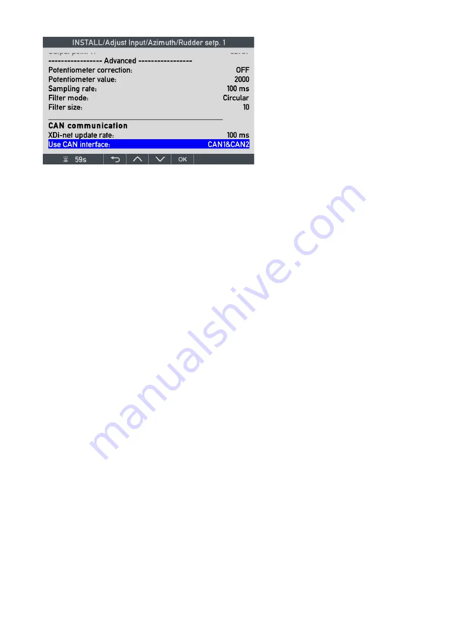
The analogue input data is filtered to avoid fluctuations due to signal noise.
11.8.1.3
Analogue data filter
Filter mode: i
s the type of filter algorithm used: off, linear or circular.
Linear:
is used for normal linear data type where the value is 0 to X or +/-X.
Circular:
is used for angular data type
s where the data range is circular, meaning that there is a “wraparound”
bX and
–X, for example the azimuth type indicator input where the +180 and -180 degree is the same
value.
In this example, the input current will change abruptly from 20 mA to 4 mA in a split second when the angle is
moved from 180
o
to -179.9
o
. To handle this, the special circular filtering algorithm is used to have a smooth
transition with normal filter function, also when this point is passed.
Filter size:
this parameter defines the number of samples used to calculate the average data value.
Filter size can be set between 0 and 100, where 0 means no filtering and 100 means that the data value is
calculated based on an average of the last 100 samples. If data presentation is fluctuating, the filter value should
be increased, but be aware that the higher the filter value, the slower the indicator will react on a change.
11.8.1.4
Data sharing on XDi-net
CAN communication
The scaled data provided by the analogue interface we have looked at may be shared on CANopen using the XDi-
net protocol. In all DEIF standard libraries this function is by default set to CAN1 & CAN2, so data is automatically
shared with another XDi “repeater” on the same CAN bust that is setup with a XDi-net input profile (usually VS01).
XDi-net update rate:
can be used to change the repetition rate on data sent on the CAN bus. Available settings
are: 50 ms,
100 ms
(default), 200 ms, 300 ms, 400 ms, 500 ms or 1000 ms. Where 100ms is the default selection.
Use CAN interface:
defines if and where XDi-net data is transmitted, settings are: OFF, CAN1, CAN2 or
CAN1&CAN2. XDi will share the data that the analogue module is calculation also if it is more than one value.
For example if the AX1 interface in a given indicator is setup to calculate all the four RPM-based data types: RPM,
%RPM, %Thrust and %Power, then all 4 types will be shared on CAN using XDi-net protocol if the CAN interface is
set active, for example to CAN1.
11.8.2
AX 1 Analogue input for RPM set point
The AX 1 module has 2 input channels that can be set up in the VS profile to represent any type of data available
as an analogue voltage, current or potentiometer input signal type. In this example, input 1 on slot 1 is set up as a
4-20 mA input for propeller RPM set point (commanded RPM). The RPM set point is +/-300 RPM equal to +/-100
% RPM, both represented by the 4-20 mA input signal.
Potentiometer correction:
this function
is only active if the input is a single high
voltage input (HV). When active, the XDi
will compensate the measurements for
the impact of the AX1 input resistance on
the potentiometer output voltage.
The potentiometer value is ohm.
Sampling rate
is default 100 ms. It may
be changed in fixed steps (50,
100
, 200,
300, 400, 500, 1000 msec.).


