DESIGNER’S HANDBOOK 4189350049C EN
Page 149 of 206
See previous chapter (AX1 used for azimuth set point) for more details.
11.9 DX1 Digital input adjust
11.9.1
DX1 digital RPM from pickup
A virtual indicator can be configured to receive digital signals directly from one or two RPM pickups as previously
described in the DX1 chapter of this document.
The DX1 extension module can be preconfigured in the VS to support either a digital input pair (bidirectional RPM)
or as one or two single direction RPM inputs.
In this example, the RPM is a single direction.
The digital RPM function calculates both the actual RPM value based on pulses per 100 revolutions, and it is also
able to calculate %RPM value based on a positive or negative RPM scaling value.
The digital RPM function can also calculate %Thrust as (%RPM)
2
and %Power as (%RPM)
3
; this is a predefined
setting in the VS, only relevant if one of those parameters are used in the virtual indicator.
(No special setup is needed for %Thrust and %Power).
The above RPM-based calculations are handled by one calculator function in the XDi, and therefore adjustments
are handled by one setup menu, described below.
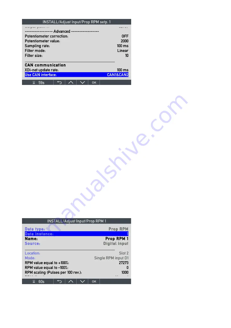
Data type
and
Data instance
have the
same function as described for the
azimuth; they define the data type and
instance to use.
Name
of the data type may be changed
via virtual keyboard.
Source is in this case the digital input from
the DX1 module located in slot 2 on the
XDi.
Mode:
is in this case single RPM input
D1, where D1 is short for digital input 1 on
the DX1 module.
Potentiometer correction:
if a
potentiometer is used for the analogue set
point, this feature may be useful (see
previous chapter for details).
Filter mode: i
n this case, the normal
linear filter type is used.
Filter size: c
an be set between 0 and
100. Increase the filter value to reduce
noise and fluctuations in the presentation.


