background image

vPad-A1 OPERATORS MANUAL

3.2  Assembly and Setup

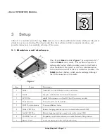
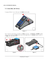
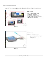
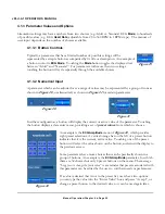
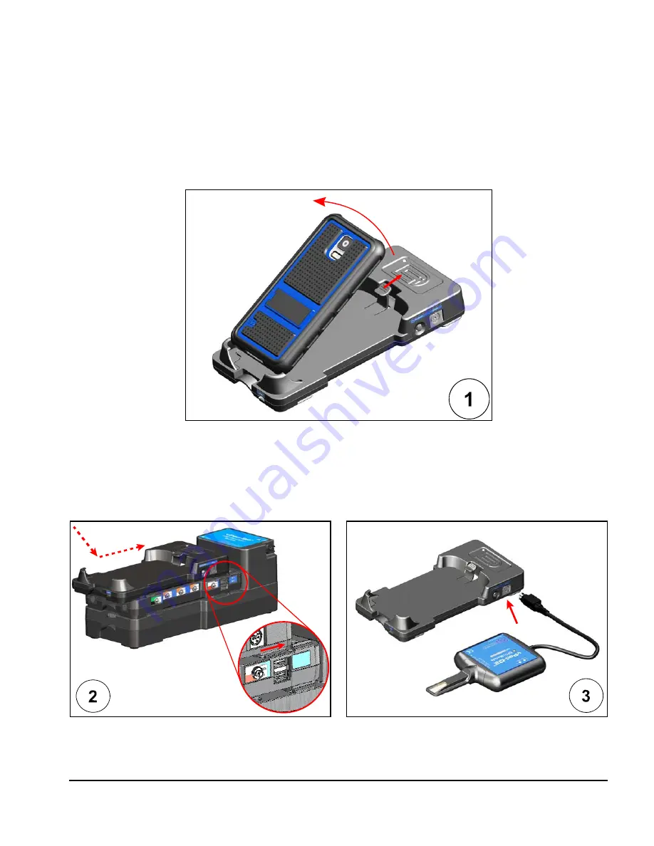
To prepare vPad-A1 for use, first remove the 

Tablet

 from its cradle. 

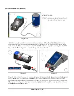
Next, connect as many simulation modules to the 

Base

 as necessary.  The 

vPad-PS

 and 

vPad-BP

 modules

slide and snap underneath the 

Base

 unit as shown in the figure below.  The 

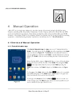
vPad-O2

 module connects to

the 

Base

 unit via the "SPO2" port. 

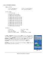
Figure 5

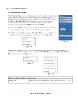
Figure 6

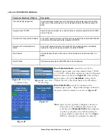
Figure 7

Setup/Chapter 3 

#

 Page 23

Содержание vPad-A1

Страница 1: ...Operating Manual MN 103c vPad A1 All in One Patient Simulator and Performance Tester ...

Страница 2: ......

Страница 3: ...ulator and Performance Tester Operating Manual 2016 2019 Datrend Systems Inc Unit 130 4020 Viking Way Richmond BC CANADA V6V 2L4 Tel 800 667 6557 North America Only or 604 291 7747 Fax 604 294 2355 e mail customerservice datrend com ...

Страница 4: ......

Страница 5: ...ducts products labelled with a distinct serial number and accessories are eligible for partial refund and or credit Non serialized parts and accessory items cables carrying cases auxiliary modules etc are not eligible for return or refund In order to receive a partial refund credit the product must not have been damaged and must be returned complete meaning all manuals cables accessories etc withi...

Страница 6: ...y such as low voltage incorrect voltage defective wiring or inadequate fuses Accident alteration abuse or misuse of the instrument Fire water damage theft war riot hostility acts of God such as hurricanes floods etc Only serialized products those items bearing a distinct serial number tag and their accessory items are covered under this warranty PHYSICAL DAMAGE CAUSED BY MISUSE OR PHYSICAL ABUSE I...

Страница 7: ... Quality Seal before you have contacted us Following these steps will help ensure that you will retain the original warranty on your instrument without interruption WARNING Unauthorized user modifications or application beyond the published specifications may result in electrical shock hazards or improper operation Datrend Systems will not be responsible for any injuries sustained due to unauthori...

Страница 8: ...Page iv ...

Страница 9: ...les and Interfaces 19 3 2 Assembly and Setup 23 4 MANUAL OPERATION 27 4 1 Overview of Manual Operation 27 4 1 1 Patient Simulator App 27 4 1 2 Parameter Selection 28 4 1 3 Parameter Values and Options 29 4 1 3 1 Button Controls 29 4 1 3 2 Numerical Input 29 4 1 3 3 Pop up and Dropdown Lists 30 4 2 ECG 32 4 2 1 General 32 4 2 2 Waveforms and Parameters 32 4 2 3 Normal Sinus Rhythm NSR 33 4 2 4 Arrh...

Страница 10: ...4 5 2 1 Static Blood Pressure 47 4 5 2 2 Dynamic Blood Pressure 47 4 5 2 3 Intra Uterine Pressure 49 4 6 Pulse Oximetry SpO2 50 4 6 1 General 50 4 6 2 Manufacturer and Model 50 4 6 3 Parameters 51 4 6 3 1 Blood Oxygen Saturation 51 4 6 3 2 Heart Rate 51 4 6 3 3 Pulse Amplitude 51 4 6 3 4 Artifact 52 4 6 4 Alarm Tests 52 4 6 4 1 Test Setup 52 4 6 4 2 Alarm State 53 4 6 4 3 Alarm Stablization 53 4 6...

Страница 11: ...bration SpO2 R Curves 67 4 8 2 4 Calibration NIBP Envelopes 69 4 8 2 5 Self Test NIBP Pulse Generator 72 5 AUTOMATION AND TEST RECORDS 73 5 1 Automated Performance Testing 73 5 1 1 Sync Mode 74 5 1 2 Test Results and Records 74 5 1 2 1 Creating Test Results 74 5 1 2 2 Reviewing Test Results 75 5 1 2 3 Entering Equipment Information 76 5 1 2 4 Creating Test Records 78 5 1 2 5 Managing Test Records ...

Страница 12: ... Association of Medical Instrumentation App Software application for a mobile device EUT Equipment Under Test The electrical device being tested Hz Hertz IEC International Electrotechnical Commission kHz kilohertz LA left arm ECG lead LL left leg ECG lead RA right arm ECG lead RL right leg ECG lead V Volt V1 V6 Precordial chest ECG leads Vrms Volts rms Definitions Page viii ...

Страница 13: ...device It may be possible to damage the Equipment Under Test EUT and or cause harm to the operator if vPad A1 is used incorrectly WARNING OPENING THE vPad A1 MAY COMPROMISE USER SAFETY REFER SERVICING TO DATREND AUTHORIZED AGENT vPad A1 is a complex instrument which contains Lithium Ion batteries and associated charging circuitry Failure to observe appropriate measures when the instrument has been...

Страница 14: ...vPad A1 OPERATORS MANUAL Definitions Page x ...

Страница 15: ...ware or app on the tablet As a modular system product capabilities will depend on the modules present specifications apply only to those modules that you have active in the system Equipment Performance Specifications 1 1 General Specifications User Interface The simulation hardware of vPad A1 is controlled by a tablet computer through a hardwired connection to the microUSB port on the tablet or al...

Страница 16: ...ht maximum all modules included 9 8 cm W x 27 5 cm L x 9 7 cm D 3 86 W x 10 83 L x 3 82 D 1 76 kg 3 88 lb Electrical Interfaces 10 standard ECG snap leads Optional externally connected ECG jacks x 10 accepts 3 mm or 4 mm plugs BP 1 and BP 2 USB Type A connector proprietary wiring TEMP 6 pin mini DIN AUX 8 pin mini DIN to optional Cardiac Output and or Mechanical Fetal Heart High level ECG Out 2 5m...

Страница 17: ...ivolt Amplitude Accuracy 2 Lead II 2 Hz Square Wave QRS width 80 msec Adult or 40 msec Neonatal Artifact 50 Hz 60 Hz Muscle Baseline wander Respiration C Rate Accuracy Better than 0 1 Normal Sinus Rhythm Rates 10 to 360 BPM presets 20 40 60 80 100 120 140 160 180 200 220 240 260 280 and 300 BPM default user re defineable Rate Accuracy Better than 0 1 Amplitudes Lead II 0 05 to 0 50 mV in 0 05 mV s...

Страница 18: ...inute PVC1 Run of 2 PVC1 Run of 5 PVC1 Run of 11 PREMATURE VENTRICULAR CONTRACTION PVC 2 Right Ventricle once Right Ventricle every 10th beat Right Ventricle Early once Right Ventricle R on T once PVC2 6 Minute PVC2 12 Minute PVC2 24 Minute PVC2 Run of 2 PVC2 Run of 5 PVC2 Run of 11 HEART BLOCKS AND CONDUCTION DEFECTS 1st Degree Heart Block Mobitz I 2nd Degree AV Block Mobitz II 2nd Degree AV Bloc...

Страница 19: ...ycardia 160 BPM Normal Sinus Rhythm GENERAL 2 Atrial Flutter Sinus Arrhythmia Miss 1 Beat 80 BPM Miss Every 10th Beat 80 BPM Miss Every 10th Beat 120 BPM Nodal Rhythm Sinus Bradycardia 60 BPM ECG Performance Tests Square Waves 0 125 Hz 2 Hz 2 5 Hz Triangle Wave 0 125 Hz 2 Hz 2 5 Hz Pulse 60 BPM or 30 BPM 60 msec Sine Waves 0 05 0 5 1 2 5 10 25 30 40 50 60 100 Hz and 150 Hz R Wave Detector Test 30 ...

Страница 20: ... all performance waveforms Respiration Rates 15 to 150 BrPM incremental with 15 customizable presets Baseline Impedance 500 1000 1500 2000 ohms on Leads I II III Apnea Selections 12 22 32 seconds and continuous 0 BPM Impedance Variation 0 to 1 0 ohms in 0 05 ohm steps 1 0 to 5 0 in 0 25 ohm steps Simulation Types Inspiration Expiration ratios of 1 5 1 4 1 3 1 2 and 1 1 and Ventilated 1 1 Lead Refe...

Страница 21: ...ic Pressures 10 to 400 mmHg 1 mmHg increments 15 customizable presets Transducer Sensitivity 5 µV V mmHg or 40 µV V mmHg I O Impedance 300 ohms 10 Excitation Voltage 2 to 16 Vp 0 to 5 kHz Dynamic Simulations Arterial 120 80 90 40 and 160 110 Radial Artery 120 80 Left Ventricle 120 0 Right Ventricle 25 0 Pulmonary Artery 25 10 Pulmonary Wedge 10 2 Right Atrium CVP 120 0 Left Atrium 14 4 Swan Ganz S...

Страница 22: ...hunt Cal Pulse 1 C for 1 second Fetal ECG Intrauterine Pressure Fetal ECG Rates 60 to 240 BPM 1 BPM increments Fetal ECG Amplitudes See NSR specification 12 preset rates user definable Fetal ECG Rate Variation Uniform Early and Late Deceleration Uniform Acceleration Pressure Waveform Bell shaped 0 50 or 0 90 mmHg Contraction Frequency Every 2 3 5 minutes or manually triggered Transducer Sensitivit...

Страница 23: ...cified accuracy of the DUT when within DUT specified range Presets 6 user definable Range of adjustment and presets may vary according to pulse oximeter specifications Heart Rate Range 20 to 300 BPM Increments 1BPM Accuracy 0 25 BPM in sync mode 1 BPM otherwise Presets 6 user definable Pulse Amplitude Range 0 to 100 Increments 1 steps Accuracy 1 Presets 6 user definable Specifications Chapter 1 Pa...

Страница 24: ...toSettings Defaults Normal Adult Hypoxia Tachycardia Bradycardia Low Perfusion No Perfusion Movement Artifact Neonate Tremor Shivering Artifact User defined Presets Unlimited Alarm Tests Defaults 5 tests Low SpO2 Low Heart Rate High Heart Rate Low Perfusion Motion Artifact User defined Alarm Tests Unlimited Specifications Chapter 1 Page 10 ...

Страница 25: ...ethod Pulse Rate 20 to 240 BPM Rate Accuracy 0 25 BPM in sync mode otherwise 1 BPM Amplitude Hi 2 0 ml nominal 1 25 mmHg into 500 ml cuff Amplitude Range 0 to 150 Amplitude Accuracy better than 0 5 BP Envelope Shift 50 mmHg max min Diastolic 15 mmHg max Systolic 275 mmHg Simulation AutoSettings Unlimited and user definable Manometer Range 0 0 to 400 0 mmHg Accuracy 0 5 mmHg Resolution 0 1 mmHg Uni...

Страница 26: ... to 200mmHg min Inflation Automatic or Manual Pressure 20 to 400mmHg Elapsed Time 30 to 600 sec Presets Pressure Elapsed Time 6 each user definable values User defined AutoSettings Unlimited Over PressureTest Inflation Automatic or Manual Range 20 to 400mmHg Release Time 1 999 sec Presets Pressure Release Time 6 each user definable values User defined AutoSettings Unlimited Specifications Chapter ...

Страница 27: ...e Clippard GE Medical Draeger Siemens Colder CPC GE Medical Protocol Systems Self Test Accessories Pressure Bulb Assembly tees into any Cuff Adapter Self system leak test hose plugged at distal end OBAC Quick Release Philips Medical Universal 5 32 I D Hose Specifications Chapter 1 Page 13 ...

Страница 28: ...vPad A1 OPERATORS MANUAL Specifications Chapter 1 Page 14 ...

Страница 29: ...cable to an individual module or to the top module in a stacked system The Base holds a 5 tablet computer referred to in this document as the Tablet which provides the simulator s Graphical User Interface GUI In addition to the Tablet the Base module provides battery power a charger port and a data communication hub which interfaces with the other three modules of the system These modules are the ...

Страница 30: ...r than setting each ECG parameter individually selection of the Hypertensive AutoSetting would set all of the parameters at once Users can configure and save a virtually unlimited number of AutoSettings Once an AutoSetting has been created it can then be used in one or more AutoSequences 2 4 AutoSequences An AutoSequence is a user configurable test template which causes vPad A1 to execute an order...

Страница 31: ... and model that generate precise signals which are matched to the chosen device In the event that a particular device is not found in the list of models tools are available in the vPad A1 App for knowledgeable users to create new custom definitions There can be a virtually unlimited number of make and model definitions stored on the tablet Overview Chapter 2 Page 17 ...

Страница 32: ...vPad A1 OPERATORS MANUAL Overview Chapter 2 Page 18 ...

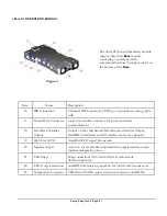
Страница 33: ...on hub to facilitate control of the test simulation modules The Tablet also has a battery which can be recharged through the USB connection to the cradle Item Name Description 1 Tablet Android 5 color LCD tablet with touch screen 2 Cradle Snap in cradle holder for Android Controller 3 SPO2 Port miniDIN8 connector to vPad O2 SpO2 accessory module 4 Power Switch Power On Off for all modules 5 LED Po...

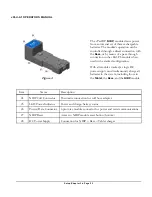
Страница 34: ...onvey light to or from pulse oximeter probes and sensors Item Name Description 11 Optical Finger Interface to pulse oximeter sensor 12 Enclosure Houses the simulation electronics 13 Red Indicator Indicates red light as detected from pulse oximeter sensor 14 Infrared Indicator Indicates infrared light as detected from pulse oximeter sensor 15 Power and Data Cable miniDIN8 cable to Base module Setup...

Страница 35: ...cations 18 Fetal Heart Cardiac Output Output to drive Mechanical Fetal Heart and Cardiac Output miniDIN8 fetal heart and CO interface boxes are optional 19 High Level ECG Amplified ECG signal phone jack 20 Injectate Adjust Access to coarse and fine adjustments for special cardiac output injectate temperature value 21 ECG Snap Snap connections 10 total for ECG monitor leads left and right side 22 E...

Страница 36: ...ules stacked a single DC power supply can simultaneously charge all batteries in the system including those in the Tablet the Base and the NIBP module Item Name Description 24 NIBP Cuff Connector Pneumatic connection for cuff hose adapter 25 LED Power Indicator Power and charge battery status 26 Power Data Connector 6 pin inter module connector for power and serial communications 27 NIBP Reset Acc...

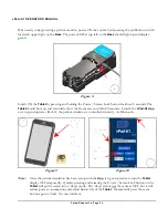
Страница 37: ...et from its cradle Next connect as many simulation modules to the Base as necessary The vPad PS and vPad BP modules slide and snap underneath the Base unit as shown in the figure below The vPad O2 module connects to the Base unit via the SPO2 port Figure 5 Figure 6 Figure 7 Setup Chapter 3 Page 23 ...

Страница 38: ...n 20 seconds Launch the vPad A1 App to set up and operate vPad A1 the patient simulator is controlled wirelessly via Bluetooth Note Once the patient simulation has been set up with the App it is good practice to turn the Tablet display OFF temporarily Quickly pressing and releasing the Power Screen Lock button on the Tablet will put its screen into a sleep mode The sleep state is not the same as O...

Страница 39: ...ad A1 vPad PS module ECG snap connectors adapter Respiration same as above Temperature TEMP connector Cardiac Output AUX CO connector IBP IBP1 IBP2 connectors vPad O2 module SpO2 probe on finger sensor with red and infrared LEDs on the same side as the module s vPad O2 label Figure 11 Figure 12 Setup Chapter 3 Page 25 ...

Страница 40: ...y connecting it to the USB Port on the the Base using the microUSB cable provided with vPad A1 If the vPad A1 will not be in use for an extended period of time exit the A1 App and switch the Base unit and the Tablet OFF To power OFF the Tablet press and hold the Power Screen Lock button until a confirmation message appears on the screen then select the appropriate response to complete the Power Of...

Страница 41: ...ing system Home screen as shown in Figure 16 The Home screen contains shortcuts to several applications installed on the Tablet An information bar at the top displays the Tablet s current status including the time of day and battery level Below the blue LCD screen of Figure 16 there is a row of three hardware buttons which are built into the face of the Tablet The elongated Home button protrudes f...

Страница 42: ...ly operating the simulator by choosing and entering new test parameters For details on quick automated testing with AutoSettings and AutoSequences see section 5 2 Test Automation On startup the App will display its Main screen as shown in Figure 17 A tabbed vertical toolbar on the left edge of the Main screen lists all the simulation categories provided though some may be initially hidden To revea...

Страница 43: ...tion a button will display the current or active value of the parameter Touching the button displays a data entry menu providing a set of preset values from which to choose An example is the ECG Amplitude menu of Figure 22 which provides eight preset selections A vertical orange bar on the left of a preset button indicates that it is the current active value Touching one of the preset buttons will...

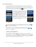
Страница 44: ...enu buttons are then re sorted If the suggested value is rejected the preset list is not changed It is possible to scroll through preset values without displaying the data entry menu of Figure 22 Referring to Figure 20 and Figure 21 instead of pressing the current value button use the and buttons to scroll through the presets Some parameters such as rate or amplitude can be adjusted incrementally ...

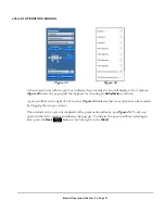
Страница 45: ...orm A gray scrollbar on the right of a list such as Figure 26 indicates that more options can be revealed by dragging the list up or down The currently active option is displayed with a green radio indicator per Figure 26 Touch any option in the list to select it and dismiss the pop up To dismiss the pop up without selecting an item press the Back button at bottom right on the Tablet Manual Operat...

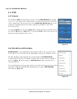
Страница 46: ...s the parameter values displayed on the screen 4 2 2 Waveforms and Parameters ECG Waveforms can be selected from the dropdown lists at the top of the screen There may be two or three list menus depending on the type of simulation in use The first dropdown menu presents the general category of ECG Waveforms Touching the first list box will display a complete list of the selections available as show...

Страница 47: ...e Note When simulation of Intra Uterine Pressure IUP section 4 5 2 3 is active the IUP simulation overrides the ECG settings of Figure 29 to output a special Fetal ECG waveform Attempts to change any ECG settings via the menu of Figure 29 will have no effect until a different Invasive Blood Pressure simulation Static or Dynamic Blood Pressure is selected 4 2 3 Normal Sinus Rhythm NSR Normal Sinus ...

Страница 48: ...ction Multifocal PVCs once Frequent Multifocal PVCs PREMATURE VENTRICULAR CONTRACTION PVC 1 Left Ventricle once Left Ventricle every 10th beat Left Ventricle Early once Left Ventricle R on T once PVC1 6 Minute PVC1 12 Minute PVC1 24 Minute PVC1 Run of 2 PVC1 Run of 5 PVC1 Run of 11 PREMATURE VENTRICULAR CONTRACTION PVC 2 Right Ventricle once Right Ventricle every 10th beat Right Ventricle Early on...

Страница 49: ...PM Normal Sinus Rhythm GENERAL 2 Atrial Flutter Sinus Arrhythmia Miss 1 Beat 80 BPM Miss Every 10th Beat 80 BPM Miss Every 10th Beat 120 BPM Nodal Rhythm Sinus Bradycardia 60 BPM The Rate of Arrhythmia simulations is fixed as Rate may be an important indicator of the cardiac disease or condition being simulated Accordingly the Rate button is greyed out when an Arrhythmia waveform is selected howev...

Страница 50: ... is adjustable between Atrial and Ventricular which affects the timing of the pacing pulse that is inserted into the paced waveform Besides the common ECG parameters Pacemaker Pulse has several additional settings that are accessible through the second dropdown list Figure 36 Figure 36 Pacer Rhythm controls the timing of the paced waveform See the tables which follow for waveform descriptions Addi...

Страница 51: ...response 75 BPM Non Function Continuous pacer pulses at 80 BPM with no heart response Pacer Pulse Amplitude controls the size of the simulated pacer pulse it can be adjusted from 700 mV to 700 mV All possible settings are listed in the preset selection menu as shown in Figure 40 This setting is not the same as the ECG Amplitude setting which controls the size of the heart beats in the simulation P...

Страница 52: ...tude parameter is available for Performance Waves simulations Rate and Mode settings are meaningless for these types of waveforms and Artifact is not applied during performance tests Once Performance Waves is selected from the first dropdown list the second dropdown menu provides a list of specific waveforms as shown below Pulse 30 BPM 60 ms Sine Wave 0 05 Hz Sine Wave 40 Hz Pulse 60 BPM 60 ms Sin...

Страница 53: ...lope 0 4375 of the QRS duration setting R wave down slope 0 5 of the QRS duration S wave up slope 0 0625 of the QRS duration Touching the QRS Duration button will display a table of preset values This table is a subset of the complete list From 8 to 20 ms in steps of 2 ms or 20 to 200 ms in steps of 10 ms 4 2 9 R Wave Detection Simpler than the QRS complex the R wave Detection signal may also be u...

Страница 54: ...the ST Level setting to a value between 150 below baseline and 150 above baseline 4 2 11 Tall T Wave The Tall T Wave simulation generates large T waves accompanying standard QRS waves Per ANSI AAMI EC 13 the QRS wave has a width of 100 ms and a QT interval of 350 ms The T wave has a sinusoidal shape 180 ms wide and T Height can be adjusted in amplitude from 0 to 150 of the QRS waveform amplitude T...

Страница 55: ...t possible to display a selector or button for every simulation parameter at the same time the Respiration menu displays in yellow a summary list of all the parameter settings which are currently in use See Figure 46 for an example of a parameters summary 4 3 2 1 Breath Rate Breath Rate controls the frequency of the Respiration simulation shown on most patient monitors as a reading in breaths per ...

Страница 56: ...s a relationship between inspiration inhalation time and expiration exhalation time which is an indicator of patient respiratory effort It can be set to one of the following options 1 1 1 2 1 3 1 4 1 5 or Ventilated 1 1 4 3 2 6 Apnea Apnea is the temporary cessation of breathing which may occur while sleeping or under anaesthesia This setting imitates the condition by suspending Respiration simula...

Страница 57: ...3 EC but the module achieves a greater accuracy of 0 01 EC for the following specific temperatures 30 32 35 37 40 and 42 EC High accuracy Temperatures are listed beneath the Temperature selection buttons 4 4 2 2 Cardiac Output Testing Cardiac Output simulations of vPad A1 are based on the thermodilution technique for hemodynamics monitoring Thermodilution is an invasive procedure that injects a kn...

Страница 58: ...perature sets the temperature of the patient s blood prior to injection of the saline It can be set to 36 37 or 38 EC 4 4 2 4 Cardiac Output Injectate Temperature Injectate Temperature sets the temperature of the saline to be injected The third dropdown menu presents the list of options as shown in Figure 52 The second to last option Spacelabs 20 EC is adjustable by means of user accessible potent...

Страница 59: ...e to Injectate Temperature and then returned to Baseline Temperature Users can choose from a set of regular curves representing a normal thermodilution routine or from a set of test curves as shown in Figure 54 A Start button will appear after choosing a Simulation Curve Pressing the button will initiate or restart the simulation Figure 54 Manual Operation Chapter 4 Page 45 ...

Страница 60: ...he dropdown lists at the top of the screen There are three modes of operation Static Blood Pressure Dynamic Blood Pressure and Intra Uterine Pressure Touching the top most menu box will present a list of the options available as shown in Figure 55 Selecting any of these options will then display a list of relevant parameters for the second list Users may set parameters as described in section 4 1 ...

Страница 61: ...ucer expected by the monitor 4 5 2 2 Dynamic Blood Pressure When Dynamic Blood Pressure DBP is selected from the upper list the module can simulate various types of IBP waveforms in synchronism with the ECG signal The second dropdown list allows selection of Channel 1 or Channel 2 Simulation Artifacts and Transducer Sensitivity Channel 1 Simulation controls the IBP1 port of vPad A1 and Channel 2 S...

Страница 62: ...m advancing When pressed the button is replaced by a button that resumes the cycle If the newly chosen Swan Ganz option is not AUTO the module will begin simulating the first waveform in the cycle above but remain in a paused state It will only advance to the next waveform in the cycle when the button is pressed To simulate noise in DBP waveforms for both channels select the Artifacts option in th...

Страница 63: ...simulation Static or Dynamic is selected Pressure ECG Timing selects a pre defined synchronization pattern which is then used for the current simulation When vPad A1 generates an IUP waveform it also changes the pulse Rate of Fetal ECG so that the fetal monitor can plot a rate waveform trend that has the same period as the pressure wave Depending on the active Pressure ECG Timing pattern the rate ...

Страница 64: ...e basic parameters it is possible to add an Artifact and to perform an Alarm Test To access the SpO2 simulation touch the SpO2 tab on the left side of the vPad A1 Main screen Figure 17 4 6 2 Manufacturer and Model vPad A1 incorporates targeted functional tests for a number of existing pulse oximetry systems organized by the name of their Manufacturer and Model To locate a particular device simply ...

Страница 65: ... press Exit to dismiss the Favourites Editor All added items will be listed in the Favourites category under Manufacturer 4 6 3 Parameters 4 6 3 1 Blood Oxygen Saturation The target Blood Oxygen Saturation SpO2 setting changes the saturation reading expected on the DUT It can be modified over the range of 30 to 100 in 1 increments Note Not all pulse oximeters are able to produce reliable measureme...

Страница 66: ...etup stage begins as soon as the SpO2 module is launched from the tabbed toolbar on the A1 Main screen At this time users should make sure that the pulse oximeter is displaying stable measurements in agreement with the active settings of Figure 68 and that an alarm is not currently active This initial state is called the Normal Condition The button launches the Alarm Test setup interface By defaul...

Страница 67: ... and the Alarm Condition A single action button appears near the centre of the interface When pressed in this initial state the action button will apply the Alarm Condition The test enters the Alarm State 4 6 4 2 Alarm State The Time to Alarm box will begin counting up in number of seconds This keeps track of the amount of time required for the pulse oximeter to respond to the Alarm Condition Pres...

Страница 68: ...meter has ceased to alarm The Time to Recover timer stops At the conclusion of the Recovery stage the test screen will appear as in Figure 75 The Time to Alarm and Time to Recover boxes now contain test data and the PASS and FAIL buttons are enabled The action button returns to the state so that users can restart the Alarm Test if desired Restarting erases existing data and returns to the Alarm St...

Страница 69: ...til the cuff fully restricts patient blood flow to the distal portions of the arm This relationship between cuff pressure blood pressure and the size of oscillometric pulses is known as an Envelope As more NIBP monitors meet regulatory approval through clinical trials they show that there is not one universal ideal Envelope as was proposed early in the history of the oscillometric NIBP technique b...

Страница 70: ...ected options on the monitor along with a cuff of appropriate size 4 7 2 4 Device The Device dropdown menu contains a list of NIBP monitor makes and models Users must select an appropriate target device to ensure that the calibrated Envelopes to be used for NIBP Simulation are suitable for the monitor s specific oscillometric blood pressure measurement algorithms Note To add a new Device not found...

Страница 71: ... Records see section 5 1 2 Test Results The interface also instructs users to initiate an NIBP measurement on the patient monitor Pressing the button will show a graphical representation of system pressure during the course of a single NIBP measurement The graph is a pop up that overlays the bottom section of the Result screen until it is dismissed The button clears the graph Pressure from that ti...

Страница 72: ...regulation It can be set from 10 to 400 mmHg in 1 mmHg increments Parameter controls are disabled in Manual Mode since users and or the DUT are in control of system pressure 4 7 3 3 Delay Time The Delay Time controls the pause duration between intermediate pressure levels in Step Mode It can be set from 1 to 600 seconds in 1 second intervals Parameter controls are disabled in Auto and Manual Mode ...

Страница 73: ...Pressure test Mode Auto The test begins pumping air into the test pneumatic system Result assignment PASS FAIL buttons are disabled until pressure reaches the Maximum Pressure In this Mode the button also activates the Maximum Pressure controls in the Result screen Users can now set a new Maximum Pressure target and apply the setting by pressing the button Users may press the and buttons to set a ...

Страница 74: ...nded at the expiration of the Delay Time countdown The test then proceeds to the next Pressure Step waits for another Delay Time duration and so on through every pressure interval until pressure reaches the Maximum Pressure Result assignment PASS FAIL buttons are subsequently enabled At Maximum Pressure vPad A1 will actively maintain the pressure level until user assigns a or Note It is recommende...

Страница 75: ...mHg in 1 mmHg increments 4 7 4 2 Release Time The Release Time designates the amount of time allowed for the pressure relief valves to vent system pressure to a safe level This value is generally specified by the manufacturer of the monitor It can be set from 1 to 999 seconds in 1 second increments 4 7 4 3 Running Over Pressure Tests Before starting an Over Pressure test first place the NIBP monit...

Страница 76: ...me countdown the End Pressure will be recorded and the tester will vent all remaining pressure and report two measurements Actual Pop Off Pressure exact pressure that caused valve trigger End Pressure system pressure at the expiration of Release Time See Figure 90 for a sample Over Pressure test report If the test does not sense a valve trigger before reaching Target Pressure then it will instead ...

Страница 77: ...sure parameter sets the initial pressure for the Leakage Rate test in Auto Mode It can be set from 20 to 400 mmHg in 1 mmHg increments This setting has no effect in Manual Mode 4 7 5 3 Test Time Test Time determines how long the Leakage Rate test will try to hold the Start Pressure in the pneumatic system without active regulation It can be set from 30 to 600 seconds in 1 second increments 4 7 5 4...

Страница 78: ... the NIBP monitor itself or alternatively from a hand pump When pressure reaches the desired level then users can start the Test Time countdown by pressing the button on the Result screen For both Modes the button is initially disabled however users can assign if for example it becomes clear that a system leak is too large to reach Start Pressure Otherwise the PASS result will be available at the ...

Страница 79: ...ce test signals If the A1 App detects that a module has been idle for some time it will automatically set that module to Standby Mode Each module will re enter Simulate Mode if the user launches its setup interface from the tabbed toolbar on the Main screen vPad O2 module SpO2 tab vPad PS module ECG RESP T C and IBP tabs vPad BP module NIBP tab To manually toggle a simulation module s power mode s...

Страница 80: ...1 Base or vPad ES tablet can use Tablet as separate handheld control interface Note Two USB options exist for compatibility with both the A1 Tablet and remote control through the vPad ES Safety Analyser using vPad Check Contact Datrend Customer Support for more information To manually change the A1 Communication interface simply use the radio buttons under Operation Mode Changing the operation mod...

Страница 81: ... information into the three text input boxes as appropriate for the new device Alternatively press the Folder Search icon to choose an existing R Curve as template A new window will show a folder list of known Manufacturers as in Figure 97 Touching any Manufacturer folder will populate the Models dropdown menu with existing devices in the same category Once the desired Model is chosen from the lis...

Страница 82: ... many devices Calibrate Red Infrared Ratio The dropdown menu contains a list of SpO2 readings that each correspond to a calibration point For example in Figure 101 the active calibration point is 97 and its associated Red Infrared R IR Ratio is 0 584 Adjust the R IR Ratio until oximeter reading agrees with the calibration point SpO2 Perform ratio adjustment for each calibration point on the SpO2 l...

Страница 83: ...tains parameters that allow the vPad BP simulator unit to generate precise pressure pulses during the course of a simulation test When creating an Envelope for a new or existing Device it is generally preferable to select as a starting point a set of simulation settings including Mode and Device that already closely resembles the desired simulation Once an appropriate selection has been made for t...

Страница 84: ...or are within acceptable tolerance of the targets P Hi P Low Different devices can have vastly different ideal Envelope shapes that conform best to their algorithms If monitor NIBP readings are unstable e g successive measurements differ by more than 5 mmHg moving the pressures x positions away from the MAP peak may improve the results To select an inflection point for editing simply press a butto...

Страница 85: ... After users have verified via the button that the displayed Envelope produces the expected readings on the target device the button will launch a Save Envelope form The form is pre populated with information extracted from the Envelope template originally selected for editing The Manufacturer and Model fields should contain the device make and model respectively both of which can be edited if nec...

Страница 86: ...ch pressure pulse generator can accurately produce the same range of pulse amplitudes during an NIBP Simulation However with its mechanical components under heavy use or simply over a period of time the generator s performance may in some cases drift away from factory conditions Since conditions of self test may be different from conditions at factory calibration failing the self test is not indic...

Страница 87: ...nerate precise calibrated signals that produce predictable results in a functional monitoring device A simulation or performance test would typically follow these four steps Setting up the desired simulations ECG Respiration SpO2 etc in the A1 App Connecting the DUT to A1 module s using signal leads cables hoses and adapters Observing the DUT for vital signs readings measurements or displays Assig...

Страница 88: ...tting was added in the AutoSequence to drive the synchronized heart beat 5 1 2 Test Results and Records When the simulation test setup is complete whether through manual input as described in chapter 4 Operation Simulation Modules or an AutoSetting or AutoSequence section 5 2 Test Automation users can record the values observed on the Device Under Test DUT A custom Test Result interface can be acc...

Страница 89: ...e Data section the DUT values are recorded with the default being the setting value if it has not been changed by the user If Comments have been made they will be recorded in the Data section The Results section will contain either PASS or FAIL If the Test Result was generated by an AutoSequence it may alternatively reported as SKIPPED or TERMINATED instead of PASS or FAIL Additional Test Results ...

Страница 90: ...111 As Equipment Information is saved A1 develops an internal equipment database for later reference so as to avoid re entering the same data in the future for the same device There is also the possibility of pre loading an equipment list as exported from for instance a CMMS system contact Datrend for further details Note Equipment Information data lookup is not case sensitive Any information save...

Страница 91: ...ch icon beside any field will display a list of text entries previously saved Besides potentially avoiding many keystrokes information field lookups have the added advantage of improving data quality and streamlining future searches in the database When ready press the button to create a new Test Record Only the Control Number and Technician ID fields are mandatory If one or more of these fields i...

Страница 92: ...entered Equipment Information and exit the Test Record creation interface This will not undo changes made to the equipment database To temporarily dismiss the Test Record creation interface while retaining the saved Equipment Information use the Back button instead Finally pressing the button will save the Test Record file to Tablet memory which can later be recalled and viewed in the vPad Record ...

Страница 93: ... AutoSetting touch the AutoSettings dropdown menu that can be found in every simulation or test setup interface Selecting an AutoSetting will set all parameters on the screen to the previously saved values There is no limit on the number of AutoSettings that may be created and stored 5 2 1 2 Creating and Editing AutoSettings It is possible to save the current active parameter setting s on a setup ...

Страница 94: ... text window To delete an AutoSetting press the icon after it is selected then use the button 5 2 2 AutoSequences An AutoSequence is a pre defined series of simulation or performance tests These tests may involve only one parameter or multiple A1 simulation modules acting in unison Each step of an AutoSequence is called a Group which consists of one or more AutoSettings pulled from various simulat...

Страница 95: ...t up vPad A1 will display the AutoSequence dropdown menu on its Main screen Figure 123 Touching the selection box will display the list of available AutoSequences By default the vPad A1 will have a number of sample AutoSequences pre installed Note that these are examples for illustrative purposes only and they can be freely revised copied or deleted by the user New AutoSequences can be added as re...

Страница 96: ...h the Groups that comprise the AutoSequence The test will sequentially activate each of the AutoSettings in the first Group then go back and display the Test Result screen for each simulation or performance test setup in the same chronological order For instance the sample AutoSequence Hypertensive has one Group of AutoSettings which contains setup information for ECG Respiration Temperature IBP S...

Страница 97: ...t any time it becomes necessary to abort the AutoSequence This will stop any testing in progress and display the View Results screen The most recently displayed Test Result entry will be marked as TERMINATED and the review window will show only the Results assigned up to the point of stoppage If the View Results screen is from concluding an AutoSequence the options to erase Result entries will not...

Страница 98: ...tensive will be edited to create a new sequence and to illustrate the normal process used to create and or change the sequence groups With the item Hypertensive visible in the AutoSequence list box touch the button and the Editor menu will be displayed The Editor menu is divided into three sections the AutoSettings selector the AutoSequence tree viewer for working with Groups and the Action Contro...

Страница 99: ...gure 17 and Figure 18 Touching the ECG sub category for instance will reveal a full list of ECG AutoSettings previously created Selecting an AutoSetting from the popup list will place it in the active AutoSequence Group if one exists Note Only one AutoSetting from any given list can be included in a single AutoSequence Group The centre section of the Editor menu is for displaying and editing AutoS...

Страница 100: ...emove the active empty Group or AutoSetting entry Permanently delete the selected AutoSequence file Save or rename the selected AutoSequence file When working with the Groups viewer and Action Controls note the following If users enter the Editor without an active AutoSequence selected the Groups list will be empty A user must then add at least a single Group before adding AutoSettings A Group can...

Страница 101: ...nges made in the Editor will not persist if users do not save the file Saving an AutoSequence without changing the pre populated file name will overwrite the selected template When AutoSequence editing is complete return to the A1 Main screen by touching the Back button by swiping left on the Editor screen Note that vPad A1 can be further automated when used in conjunction with vPad Check and the ...

Страница 102: ...vPad A1 OPERATORS MANUAL Automation and Test Records Chapter 5 Page 88 ...

Страница 103: ...zed service agent This unit may contain hazardous voltages which may cause injury if correct service procedures are not followed For calibration or service assistance contact Datrend for a Return Materials Authorization RMA number and the location of the nearest Service Facility Datrend Systems Inc Unit 130 4020 Viking Way Richmond BC CANADA V6V 2L4 Tel 604 291 7747 or 800 667 6557 Fax 604 294 235...

Страница 104: ...vPad A1 OPERATORS MANUAL Maintenance Chapter 6 Page 90 ...

Страница 105: ...st setup and user entered numerical data as well as additional comments Note The sample Test Record was generated in Demo Mode Hence all unit identifiers under vPad ID contain the word DEMO A normal record will contain real vPad IDs matching the serial number decals on each Simulator Tester Unit along with the date of the latest calibration Appendix A Page 91 ...

Страница 106: ...0624700 Location CARDIAC CARE UNIT Facility CITY GENERAL Technician ID RW Tech Time hrs 0 6 min 35 Overall Result PASS Signature ____________________________ Date __________ Detailed Test Data _______________________________________________________ Task Normal sinus rhythm Axis Deviation Intermediate Normal Axis Amplitude 2 0 mV Rate 80 BPM Artifact OFF Mode Adult Data Amplitude 2 2 mV Rate 79 BPM...

Страница 107: ...vPad A1 OPERATORS MANUAL Appendix A Page 93 ...

Страница 108: ......

Отзывы: