


3-5. Disassembly, Reassembly and Lubrication
CLP-621 & CLP-631
3-16
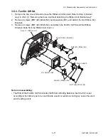
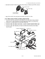
3-5-8. Ribbon Tension Shaft F SA and Tension Sensor SA
Caution:
DO NOT disassemble the Tension Base Adjust Cam and tension adjust screw (PH,
M1.7x4) unless you need to replace them.
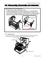
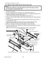
1. Open the Top Cover SA.
2. Remove the Ribbon Sensor F Unit. Refer to 3-5-7 “Ribbon Sensor F/R Unit”.
3. Remove 2 screws (NO.0, TFH (BT), M2x4 (NI)) at both ends, and detach the Ribbon Tension
Shaft F SA and Ribbon Guide Roller Bush 2 (2 pcs.).
4. Peel off the Static Eliminator Sheet from the Ribbon Tension Shaft F SA.
5. Remove 1 screw (PH (PW), M2x8), and detach the Tension Adjust Lever F Block and Tension
Adjust Shaft.
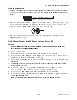
6. Remove the Ribbon Sub Adjust Lever F SA and Ribbon Tension Spring F (2 pcs.) from the
Tension Adjust Lever F SA.
7. Remove the tension adjust screw (PH, M1.7x4) from the Tension Adjust Lever F SA.
Note:
Do not remove this tension adjust screw unless you need to replace it.
8. Remove 2 screws (NO.0, TFH, M2x3 (NI)) and detach the Tension Sensor SA.
9. Remove 1 screw (NO.0, TFH, M2x3 (NI)), and detach the Tension Base Adjust Cam from the
Ribbon Sensor Frame F SA.
Note:
Do not remove the Tension Base Adjust Cam unless you need to replace it.
Cam, Tension Base Adjust
Bush 2, Ribbon
Guide Roller
Bush 2, Ribbon Guide Roller
SA, Ribbon Tension Shaft F
Sheet, Static Eliminator 621
NO.0, TFH (BH),
M2x4 (NI)
NO.0, TFH (BH),
M2x4 (NI)
SA, Ribbon Sensor Frame F
Spring F, Ribbon Tension
SA, Ribbon Sub
Adjust Lever F
SA, Tension Adjust Lever F
SA, Tension
Sensor
NO.0, TFH,
M2x3 (NI)
PH (PW), M2x8
PH, M1.7x4
Shaft, Tension Adjust
Содержание CLP-621
Страница 1: ...Technical Manual CLP 621 CLP 631 Thermal Transfer Barcode Label Printer JM74961 00F 1 00E 0701...
Страница 2: ...CLP 621 CLP 631 ii Copyright 2007 by CITIZEN SYSTEMS JAPAN CO LTD...
Страница 4: ...CHAPTER 1 SPECIFICATIONS CLP 621 CLP 631...
Страница 13: ...CHAPTER 2 OPERATING PRINCIPLES CLP 621 CLP 631...
Страница 68: ...2 5 Power Supply CLP 621 CLP 631 2 56 N1 N2 N3 N4 BLOCK A BLOCK E BLOCK B BLOCK C BLOCK D 120V type...
Страница 69: ...2 5 Power Supply 2 57 CLP 621 CLP 631 N1 N2 N3 N4 Block A Block B Block C Block E Block D 220 240V type...
Страница 73: ...CHAPTER 3 DISASSEMBLY AND MAINTENANCE CLP 621 CLP 631...
Страница 126: ...CLP 621 CLP 631 CHAPTER 4 TROUBLESHOOTING...
Страница 138: ...CLP 621 CLP 631 CHAPTER 5 PARTS LISTS...
Страница 143: ...Chapter 5 Parts Lists CLP 621 CLP 631 5 6 DRAWING NO 1 General Assembly Rev 0 1 7 8 2 3 4 2 10 11 12 9 5 2 13 14 10...
Страница 163: ...Chapter 5 Parts Lists CLP 621 CLP 631 5 26 DRAWING NO 6 Sensor U Unit Rev 0 4 16 3 2 1 9 10 11 5 8 6 12 7 13 14 15...
Страница 166: ...Chapter 5 Parts Lists CLP 621 CLP 631 5 29 DRAWING NO 7 Control Panel Unit Rev 0 4 3 2 1 5...
Страница 174: ...Chapter 5 Parts Lists CLP 621 CLP 631 5 37 DRAWING NO 9 Ribbon Unit Fan SA2 Rev 0 1 2 4 3 5 6 3...
Страница 177: ...Chapter 5 Parts Lists CLP 621 CLP 631 5 40 DRAWING NO 10 Accessories Rev 0 3 2 4 1...
Страница 179: ...CHAPTER 6 CIRCUIT DIAGRAMS CLP 621 CLP 631...
Страница 208: ...APPENDICES CLP 621 CLP 631...
Страница 211: ...B Mounting Diagrams B Mounting Diagrams B Mounting Diagrams CLP 621 CLP 631 AP 4 AP 4 B 1 Main PCB Main PCB Parts side...
Страница 212: ...B Mounting Diagrams AP 5 CLP 621 CLP 631 Main PCB Solder side...
Страница 213: ...B Mounting Diagrams CLP 621 CLP 631 AP 6 AP 6 B 2 Power Supply PCB 120V 220V B 2 Power Supply PCB 120V 220V...
Страница 214: ...B Mounting Diagrams AP 7 CLP 621 CLP 631 B 3 Ribbon Main PCB Parts side Solder side...
Страница 217: ......


