


4-2. Troubleshooting
CL
P-
621 & CLP-631
4-6
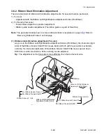
4-2-2. Media-feed Problems
Symptoms
Checks
Remedies
No media feed
1. Is the connector CN5 for PF motor
connected firmly?
2. Is the connector CN10 for Power
Supply Unit connected firmly?
3. Is +24V supplied to the test point T18?
4. Failure in the control circuit or in the
paper feed motor driver.
5. Does the PF motor work?
1. Re-connect it firmly.
2. Re-connect it firmly.
3. Replace the Power Supply Unit.
4. Replace the Main PCB Unit.
5. Replace the Motor SA.
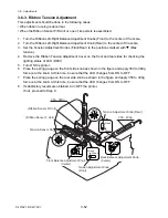
Irregular media feed
pitch
1. Is the connector CN5 for PF motor
connected firmly?
2. Is dust or other foreign matter on the
platen?
3. Does the media feed mechanism work
smoothly?
4. Failure in the control circuit or in the
paper feed motor driver.
1. Re-connect it firmly.
2. Remove dust or foreign matter.
3. Check, clean and lubricate
mechanical parts.
Note:
Refer to Chap. 3
"Disassembly and Maintenance".
4. Replace the Main PCB Unit.
Media jamming
1. Is media set correctly?
2. Is the media being used within
manufacturer's specifications?
3. Check the media feed mechanism and
media path for dust or other foreign
matter.
1. Set media correctly.
2. Use media within manufacturer's
specifications.
3. Remove dust or foreign matter.
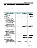
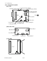
Voltage test points:
Bottom right of the Main PCB Unit
Test point is a rectangle dipped pattern on the
component side of the Main PCB Unit.
T16 For
+5V Control
T17 For
+3.3V
Logic
T18 For
+24V Drive
T19
For +1.5V For CPU only
CN10
TP18
+24V
TP17
+3.3V
TP16
+5V
TP19
+1.5V
Содержание CLP-621
Страница 1: ...Technical Manual CLP 621 CLP 631 Thermal Transfer Barcode Label Printer JM74961 00F 1 00E 0701...
Страница 2: ...CLP 621 CLP 631 ii Copyright 2007 by CITIZEN SYSTEMS JAPAN CO LTD...
Страница 4: ...CHAPTER 1 SPECIFICATIONS CLP 621 CLP 631...
Страница 13: ...CHAPTER 2 OPERATING PRINCIPLES CLP 621 CLP 631...
Страница 68: ...2 5 Power Supply CLP 621 CLP 631 2 56 N1 N2 N3 N4 BLOCK A BLOCK E BLOCK B BLOCK C BLOCK D 120V type...
Страница 69: ...2 5 Power Supply 2 57 CLP 621 CLP 631 N1 N2 N3 N4 Block A Block B Block C Block E Block D 220 240V type...
Страница 73: ...CHAPTER 3 DISASSEMBLY AND MAINTENANCE CLP 621 CLP 631...
Страница 126: ...CLP 621 CLP 631 CHAPTER 4 TROUBLESHOOTING...
Страница 138: ...CLP 621 CLP 631 CHAPTER 5 PARTS LISTS...
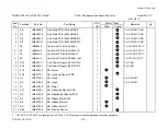
Страница 143: ...Chapter 5 Parts Lists CLP 621 CLP 631 5 6 DRAWING NO 1 General Assembly Rev 0 1 7 8 2 3 4 2 10 11 12 9 5 2 13 14 10...
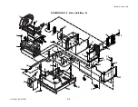
Страница 163: ...Chapter 5 Parts Lists CLP 621 CLP 631 5 26 DRAWING NO 6 Sensor U Unit Rev 0 4 16 3 2 1 9 10 11 5 8 6 12 7 13 14 15...
Страница 166: ...Chapter 5 Parts Lists CLP 621 CLP 631 5 29 DRAWING NO 7 Control Panel Unit Rev 0 4 3 2 1 5...
Страница 174: ...Chapter 5 Parts Lists CLP 621 CLP 631 5 37 DRAWING NO 9 Ribbon Unit Fan SA2 Rev 0 1 2 4 3 5 6 3...
Страница 177: ...Chapter 5 Parts Lists CLP 621 CLP 631 5 40 DRAWING NO 10 Accessories Rev 0 3 2 4 1...
Страница 179: ...CHAPTER 6 CIRCUIT DIAGRAMS CLP 621 CLP 631...
Страница 208: ...APPENDICES CLP 621 CLP 631...
Страница 211: ...B Mounting Diagrams B Mounting Diagrams B Mounting Diagrams CLP 621 CLP 631 AP 4 AP 4 B 1 Main PCB Main PCB Parts side...
Страница 212: ...B Mounting Diagrams AP 5 CLP 621 CLP 631 Main PCB Solder side...
Страница 213: ...B Mounting Diagrams CLP 621 CLP 631 AP 6 AP 6 B 2 Power Supply PCB 120V 220V B 2 Power Supply PCB 120V 220V...
Страница 214: ...B Mounting Diagrams AP 7 CLP 621 CLP 631 B 3 Ribbon Main PCB Parts side Solder side...
Страница 217: ......


