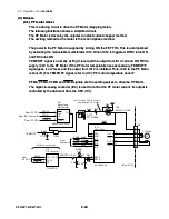


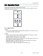


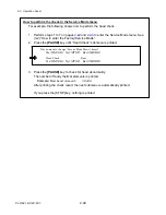


2-3. Operation Panel
CLP-621 & CLP-631
2-42
2-42
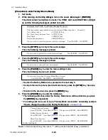
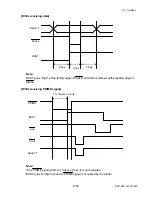
[Procedure to enter Factory/Service Mode]
[Procedure to enter Factory/Service Mode]
1. Set
media.
1. Set
media.
2. While pressing and holding
all keys
, turn on the power. (
ALL keys + [POWER]
)
2. While pressing and holding
all keys
, turn on the power. (
ALL keys + [POWER]
)
The printer enters Factory/Service mode. The PRINT LED and CONDITION LED light
up and the following message is printed on media.
The printer enters Factory/Service mode. The PRINT LED and CONDITION LED light
up and the following message is printed on media.
3. Press
the
[STOP]
key to skip to the next message.
3. Press
the
[STOP]
key to skip to the next message.
Then, the following message is printed.
Then, the following message is printed.
4. Press
the
[STOP]
key to skip to the next message.
4. Press
the
[STOP]
key to skip to the next message.
Then, the following message is printed.
Then, the following message is printed.
5. Press
the
[PAUSE]
key to enter the menu settings mode.
5. Press
the
[PAUSE]
key to enter the menu settings mode.
Then, the following top menu is printed.
Then, the following top menu is printed.
• To enter the Factory Mode menu, proceed to the next step 6.
• To enter the Factory Mode menu, proceed to the next step 6.
• To skip to the next top menu (Service Mode menu), press the
[STOP]
key. See step
7.
• To skip to the next top menu (Service Mode menu), press the
[STOP]
key. See step
7.
• To return to the previous one, press the
[MODE]
key.
• To return to the previous one, press the
[MODE]
key.
6. Press
the
[PAUSE]
key to enter the submenus.
6. Press
the
[PAUSE]
key to enter the submenus.
* The following submenus under the Factory Mode menu will be printed as you press
the
[PAUSE]
key repeatedly.
* The following submenus under the Factory Mode menu will be printed as you press
the
[PAUSE]
key repeatedly.
* For setting each item, see (3-3)-(a) “Factory Mode menu table”, and setting example
“How to change the value in the Factory Mode menu
* For setting each item, see (3-3)-(a) “Factory Mode menu table”, and setting example
“How to change the value in the Factory Mode menu” on page
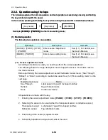
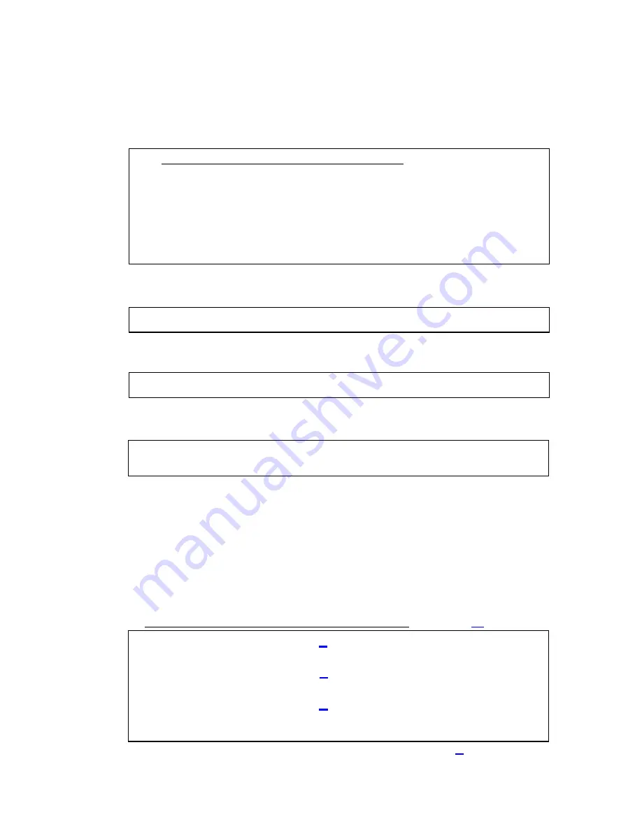
Citizen CLP-621 VuePrint Menu System
The four control panel buttons are used to select different options. Generally:
Yes / Select / Save
= PAUSE (P) key
No / Next Item / Increase Item = STOP (S) key
Next Digit
= FEED (F) key
Exit to previous menu
= MODE (M) key
Do you want to reset this printer to factory settings? Yes=(PAUSE) No=(STOP)
Do you want to print the current menu settings?
Yes=(PAUSE) No=(STOP)
Do you want to change the menu settings?
Yes=(PAUSE) No=(STOP)
Through Sensor Position
+000
Save=(PAUSE) Next Digit=(FEED) Change value=(STOP) Exit=(MODE)
Reflect Sensor Position
+000
Save=(PAUSE) Next Digit=(FEED) Change value=(STOP) Exit=(MODE)
Mach Tear Position
+000
Save=(PAUSE) Next Digit=(FEED) Change value=(STOP) Exit=(MODE)
(to be continued)
Do you want to change “Factory Mode Menu” items?
Yes=(PAUSE) No=(STOP) Exit=(MODE)
Note:
In the actual printing, the cursor “^” will be printed instead of “ (underline)”.
Содержание CLP-621
Страница 1: ...Technical Manual CLP 621 CLP 631 Thermal Transfer Barcode Label Printer JM74961 00F 1 00E 0701...
Страница 2: ...CLP 621 CLP 631 ii Copyright 2007 by CITIZEN SYSTEMS JAPAN CO LTD...
Страница 4: ...CHAPTER 1 SPECIFICATIONS CLP 621 CLP 631...
Страница 13: ...CHAPTER 2 OPERATING PRINCIPLES CLP 621 CLP 631...
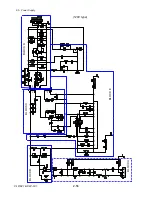
Страница 68: ...2 5 Power Supply CLP 621 CLP 631 2 56 N1 N2 N3 N4 BLOCK A BLOCK E BLOCK B BLOCK C BLOCK D 120V type...
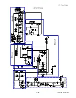
Страница 69: ...2 5 Power Supply 2 57 CLP 621 CLP 631 N1 N2 N3 N4 Block A Block B Block C Block E Block D 220 240V type...
Страница 73: ...CHAPTER 3 DISASSEMBLY AND MAINTENANCE CLP 621 CLP 631...
Страница 126: ...CLP 621 CLP 631 CHAPTER 4 TROUBLESHOOTING...
Страница 138: ...CLP 621 CLP 631 CHAPTER 5 PARTS LISTS...
Страница 143: ...Chapter 5 Parts Lists CLP 621 CLP 631 5 6 DRAWING NO 1 General Assembly Rev 0 1 7 8 2 3 4 2 10 11 12 9 5 2 13 14 10...
Страница 163: ...Chapter 5 Parts Lists CLP 621 CLP 631 5 26 DRAWING NO 6 Sensor U Unit Rev 0 4 16 3 2 1 9 10 11 5 8 6 12 7 13 14 15...
Страница 166: ...Chapter 5 Parts Lists CLP 621 CLP 631 5 29 DRAWING NO 7 Control Panel Unit Rev 0 4 3 2 1 5...
Страница 174: ...Chapter 5 Parts Lists CLP 621 CLP 631 5 37 DRAWING NO 9 Ribbon Unit Fan SA2 Rev 0 1 2 4 3 5 6 3...
Страница 177: ...Chapter 5 Parts Lists CLP 621 CLP 631 5 40 DRAWING NO 10 Accessories Rev 0 3 2 4 1...
Страница 179: ...CHAPTER 6 CIRCUIT DIAGRAMS CLP 621 CLP 631...
Страница 208: ...APPENDICES CLP 621 CLP 631...
Страница 211: ...B Mounting Diagrams B Mounting Diagrams B Mounting Diagrams CLP 621 CLP 631 AP 4 AP 4 B 1 Main PCB Main PCB Parts side...
Страница 212: ...B Mounting Diagrams AP 5 CLP 621 CLP 631 Main PCB Solder side...
Страница 213: ...B Mounting Diagrams CLP 621 CLP 631 AP 6 AP 6 B 2 Power Supply PCB 120V 220V B 2 Power Supply PCB 120V 220V...
Страница 214: ...B Mounting Diagrams AP 7 CLP 621 CLP 631 B 3 Ribbon Main PCB Parts side Solder side...
Страница 217: ......


