


3-5. Disassembly, Reassembly and Lubrication
CLP-621 & CLP-631
3-34
3-5-19. Head Adjust Cam and Head Balance Cam
1. Remove the Mechanism Unit. Refer to 3-5-13 “Mechanism Unit and Case L”.
2. Remove the Head Block. Refer to 3-5-17 “Head Block and PF Unit”.
3. Remove the Head Unit. Refer to 3-5-18 (1) “Head Unit”.
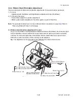
4. Remove the Head L Spring (short one) and the Head R Spring (long one).
5. Remove the Head Balance Cam as follows:
1) Set the Head Balance Cam (media width adjustment dial) to the location “0” and remove
the Head Balance Lever.
2) Remove 1 screw (PH, M3x6), and detach the Head Balance Cam and the Head Balance
Cam Pivot.
6. Remove 1 screw (PH, M3x6), and detach the Head Adjust SA.
Note:
The Head Adjust Shim(s) may be inserted for adjusting height, depending on the printer
to be used. It may be inserted at the factory to obtain correct adjustable range of the
Media Thickness Adjustment Dial. (Reference information is written in 3-6-4
“Maintenance Information - Head Adjust Shim”.)
If the shim(s) is(are) inserted, assemble it(them) as it was(were).
7. Remove 1 screw (PH, M3x5) and detach the Guide Sensor U Holder from the Head Holder
Base SA.
FLOIL G-311S
Spring, Head L
(Short)
Spring, Head R (Long)
Lever, Head Balance
PH, M3x6
Pivot, Head Balance Cam
Cam, Head Balance
(Media Width Adjustment Dial)
SA, Head Holder Base
PH, M3x6
Holder, Guide Sensor U
PH, M3x5
Label 2, Caution
Head
Label 7, Caution
Head
SA, Head Adjust
Shim, Head Adjust
May be assembled
in some printers
for height adjustment.
Note on reassembling:
• When assembling, apply G-311S to the Head Balance Cam Pivot surface.
Содержание CLP-621
Страница 1: ...Technical Manual CLP 621 CLP 631 Thermal Transfer Barcode Label Printer JM74961 00F 1 00E 0701...
Страница 2: ...CLP 621 CLP 631 ii Copyright 2007 by CITIZEN SYSTEMS JAPAN CO LTD...
Страница 4: ...CHAPTER 1 SPECIFICATIONS CLP 621 CLP 631...
Страница 13: ...CHAPTER 2 OPERATING PRINCIPLES CLP 621 CLP 631...
Страница 68: ...2 5 Power Supply CLP 621 CLP 631 2 56 N1 N2 N3 N4 BLOCK A BLOCK E BLOCK B BLOCK C BLOCK D 120V type...
Страница 69: ...2 5 Power Supply 2 57 CLP 621 CLP 631 N1 N2 N3 N4 Block A Block B Block C Block E Block D 220 240V type...
Страница 73: ...CHAPTER 3 DISASSEMBLY AND MAINTENANCE CLP 621 CLP 631...
Страница 126: ...CLP 621 CLP 631 CHAPTER 4 TROUBLESHOOTING...
Страница 138: ...CLP 621 CLP 631 CHAPTER 5 PARTS LISTS...
Страница 143: ...Chapter 5 Parts Lists CLP 621 CLP 631 5 6 DRAWING NO 1 General Assembly Rev 0 1 7 8 2 3 4 2 10 11 12 9 5 2 13 14 10...
Страница 163: ...Chapter 5 Parts Lists CLP 621 CLP 631 5 26 DRAWING NO 6 Sensor U Unit Rev 0 4 16 3 2 1 9 10 11 5 8 6 12 7 13 14 15...
Страница 166: ...Chapter 5 Parts Lists CLP 621 CLP 631 5 29 DRAWING NO 7 Control Panel Unit Rev 0 4 3 2 1 5...
Страница 174: ...Chapter 5 Parts Lists CLP 621 CLP 631 5 37 DRAWING NO 9 Ribbon Unit Fan SA2 Rev 0 1 2 4 3 5 6 3...
Страница 177: ...Chapter 5 Parts Lists CLP 621 CLP 631 5 40 DRAWING NO 10 Accessories Rev 0 3 2 4 1...
Страница 179: ...CHAPTER 6 CIRCUIT DIAGRAMS CLP 621 CLP 631...
Страница 208: ...APPENDICES CLP 621 CLP 631...
Страница 211: ...B Mounting Diagrams B Mounting Diagrams B Mounting Diagrams CLP 621 CLP 631 AP 4 AP 4 B 1 Main PCB Main PCB Parts side...
Страница 212: ...B Mounting Diagrams AP 5 CLP 621 CLP 631 Main PCB Solder side...
Страница 213: ...B Mounting Diagrams CLP 621 CLP 631 AP 6 AP 6 B 2 Power Supply PCB 120V 220V B 2 Power Supply PCB 120V 220V...
Страница 214: ...B Mounting Diagrams AP 7 CLP 621 CLP 631 B 3 Ribbon Main PCB Parts side Solder side...
Страница 217: ......


