


2-2. Operation of Control Parts
2-25
CLP-621 & CLP-631
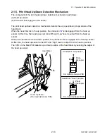
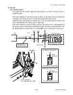
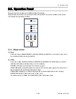
[Tension Sensor PCB]
Tension Sensor
2
3
1
CN901
PI901
R901
C902
C901
+3.3V
4
+3.3V
R902
D901
Take-up side
[Tension Sensor PCB]
2
3
1
4
Supply side
2
3
1
CN704
4
(Same as above circuit)
CN901
2
3
1
CN705
4
[Ribbon Main PCB]
+3.3V
R727
+3.3V
C719
C720
2
4
IC708A
18
17
CN701
IC707A
6
7
(Same as above circuit)
IC11
Custom IC
SENS_A
97
PM2
10
9
SENS_B
98
PM3
[Main PCB]
CN8
R728
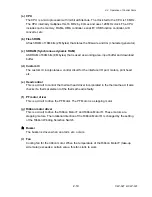
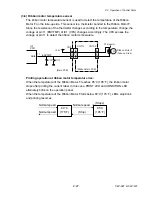
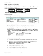
(3-4) Head temperature sensor
The head temperature sensor is used to detect the temperature of the thermal head. This
sensor is a thermistor incorporated in the Head SA. Since the resistance of the thermistor
changes according to the temperature change, the voltage at pin 7 (HDTMP) of IC1 (CPU)
changes accordingly. The CPU senses the voltage at pin 7 to detect the head temperature.
According to the temperature of the print head, the CPU controls the printing pulse width
applied to the thermal elements to keep the printing density constant.
CN4
Thermal Head
5,6,8,11,12,20,22
HDTHM2
+3.3V
19
R85
HDTMP
IC1
CPU
ANI2
7
Head Temp.
Thermistor
[Main PCB]
21
HDTHM1
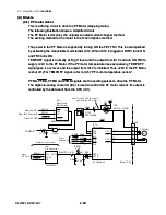
Printing operation at the head temperature rise:
When the head temperature reaches 65
°
C (149
°
F), printing stops after printing the current
label. In this case, PRINT LED and CONDITION LED simultaneously blink on the
operation panel. When the temperature of the Head SA falls below 55
°
C (131
°
F), LEDs
stop blinking and printing resumes.
55
°
C
(131
°
F)
65
°
C
(149
°
F)
Normal speed
(Stop)
Normal speed
Normal speed
(Stops)
Содержание CLP-621
Страница 1: ...Technical Manual CLP 621 CLP 631 Thermal Transfer Barcode Label Printer JM74961 00F 1 00E 0701...
Страница 2: ...CLP 621 CLP 631 ii Copyright 2007 by CITIZEN SYSTEMS JAPAN CO LTD...
Страница 4: ...CHAPTER 1 SPECIFICATIONS CLP 621 CLP 631...
Страница 13: ...CHAPTER 2 OPERATING PRINCIPLES CLP 621 CLP 631...
Страница 68: ...2 5 Power Supply CLP 621 CLP 631 2 56 N1 N2 N3 N4 BLOCK A BLOCK E BLOCK B BLOCK C BLOCK D 120V type...
Страница 69: ...2 5 Power Supply 2 57 CLP 621 CLP 631 N1 N2 N3 N4 Block A Block B Block C Block E Block D 220 240V type...
Страница 73: ...CHAPTER 3 DISASSEMBLY AND MAINTENANCE CLP 621 CLP 631...
Страница 126: ...CLP 621 CLP 631 CHAPTER 4 TROUBLESHOOTING...
Страница 138: ...CLP 621 CLP 631 CHAPTER 5 PARTS LISTS...
Страница 143: ...Chapter 5 Parts Lists CLP 621 CLP 631 5 6 DRAWING NO 1 General Assembly Rev 0 1 7 8 2 3 4 2 10 11 12 9 5 2 13 14 10...
Страница 163: ...Chapter 5 Parts Lists CLP 621 CLP 631 5 26 DRAWING NO 6 Sensor U Unit Rev 0 4 16 3 2 1 9 10 11 5 8 6 12 7 13 14 15...
Страница 166: ...Chapter 5 Parts Lists CLP 621 CLP 631 5 29 DRAWING NO 7 Control Panel Unit Rev 0 4 3 2 1 5...
Страница 174: ...Chapter 5 Parts Lists CLP 621 CLP 631 5 37 DRAWING NO 9 Ribbon Unit Fan SA2 Rev 0 1 2 4 3 5 6 3...
Страница 177: ...Chapter 5 Parts Lists CLP 621 CLP 631 5 40 DRAWING NO 10 Accessories Rev 0 3 2 4 1...
Страница 179: ...CHAPTER 6 CIRCUIT DIAGRAMS CLP 621 CLP 631...
Страница 208: ...APPENDICES CLP 621 CLP 631...
Страница 211: ...B Mounting Diagrams B Mounting Diagrams B Mounting Diagrams CLP 621 CLP 631 AP 4 AP 4 B 1 Main PCB Main PCB Parts side...
Страница 212: ...B Mounting Diagrams AP 5 CLP 621 CLP 631 Main PCB Solder side...
Страница 213: ...B Mounting Diagrams CLP 621 CLP 631 AP 6 AP 6 B 2 Power Supply PCB 120V 220V B 2 Power Supply PCB 120V 220V...
Страница 214: ...B Mounting Diagrams AP 7 CLP 621 CLP 631 B 3 Ribbon Main PCB Parts side Solder side...
Страница 217: ......


