


3-1. Maintenance Precautions
CLP-621 & CLP-631
3-4
3-1. Maintenance Precautions
WARNINGS
(1) Before starting disassembly/reassembly or mechanical adjustment, be sure to disconnect
the power cord from the power source.
(2) Do not replace a fuse with the power switch turned on.
(3) The fuse is provided to prevent fire, and damage to the Power Supply Unit.
When replacing it, use the same rating and type.
(4) The main plug on this equipment must be used to disconnect main power.
Please ensure that the socket outlet is installed near the equipment and is easily
accessible.
Observe the following in maintenance work:
CAUTIONS
(1) Do not disassemble/reassemble or adjust the machine, if it functions properly.
Particularly, do not loosen screws on any component, unless necessary.
(2) After completing an inspection and before turning on the power, be sure to check that there
is no abnormality.
(3) Never try to print without media.
(4) Check that the media is properly set.
(5) Do not lay anything on the cover or lean against it during maintenance or while the printer is
in operation.
(6) During maintenance, be careful not to leave parts or screws unattached or loose inside the
printer.
(7) When handling a printed circuit board, do not use gloves, etc., which can easily cause static
electricity. Since ICs, such as CPU, RAM and ROM, might be destroyed by static electricity,
do not touch lead wires or windows unnecessarily.
(8) Do not put the printed circuit boards directly on the printer or on the floor.
(9) When disassembling or reassembling, check wires for any damage and do not pinch or
damage them. Also, run wires as they were.
Содержание CLP-621
Страница 1: ...Technical Manual CLP 621 CLP 631 Thermal Transfer Barcode Label Printer JM74961 00F 1 00E 0701...
Страница 2: ...CLP 621 CLP 631 ii Copyright 2007 by CITIZEN SYSTEMS JAPAN CO LTD...
Страница 4: ...CHAPTER 1 SPECIFICATIONS CLP 621 CLP 631...
Страница 13: ...CHAPTER 2 OPERATING PRINCIPLES CLP 621 CLP 631...
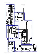
Страница 68: ...2 5 Power Supply CLP 621 CLP 631 2 56 N1 N2 N3 N4 BLOCK A BLOCK E BLOCK B BLOCK C BLOCK D 120V type...
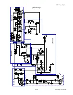
Страница 69: ...2 5 Power Supply 2 57 CLP 621 CLP 631 N1 N2 N3 N4 Block A Block B Block C Block E Block D 220 240V type...
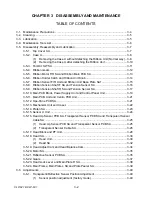
Страница 73: ...CHAPTER 3 DISASSEMBLY AND MAINTENANCE CLP 621 CLP 631...
Страница 126: ...CLP 621 CLP 631 CHAPTER 4 TROUBLESHOOTING...
Страница 138: ...CLP 621 CLP 631 CHAPTER 5 PARTS LISTS...
Страница 143: ...Chapter 5 Parts Lists CLP 621 CLP 631 5 6 DRAWING NO 1 General Assembly Rev 0 1 7 8 2 3 4 2 10 11 12 9 5 2 13 14 10...
Страница 163: ...Chapter 5 Parts Lists CLP 621 CLP 631 5 26 DRAWING NO 6 Sensor U Unit Rev 0 4 16 3 2 1 9 10 11 5 8 6 12 7 13 14 15...
Страница 166: ...Chapter 5 Parts Lists CLP 621 CLP 631 5 29 DRAWING NO 7 Control Panel Unit Rev 0 4 3 2 1 5...
Страница 174: ...Chapter 5 Parts Lists CLP 621 CLP 631 5 37 DRAWING NO 9 Ribbon Unit Fan SA2 Rev 0 1 2 4 3 5 6 3...
Страница 177: ...Chapter 5 Parts Lists CLP 621 CLP 631 5 40 DRAWING NO 10 Accessories Rev 0 3 2 4 1...
Страница 179: ...CHAPTER 6 CIRCUIT DIAGRAMS CLP 621 CLP 631...
Страница 208: ...APPENDICES CLP 621 CLP 631...
Страница 211: ...B Mounting Diagrams B Mounting Diagrams B Mounting Diagrams CLP 621 CLP 631 AP 4 AP 4 B 1 Main PCB Main PCB Parts side...
Страница 212: ...B Mounting Diagrams AP 5 CLP 621 CLP 631 Main PCB Solder side...
Страница 213: ...B Mounting Diagrams CLP 621 CLP 631 AP 6 AP 6 B 2 Power Supply PCB 120V 220V B 2 Power Supply PCB 120V 220V...
Страница 214: ...B Mounting Diagrams AP 7 CLP 621 CLP 631 B 3 Ribbon Main PCB Parts side Solder side...
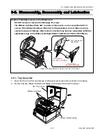
Страница 217: ......


