


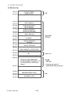


2-2. Operation of Control Parts
2-2. Operation of Control Parts
CLP-621 & CLP-631
2-16
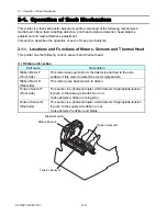
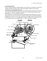
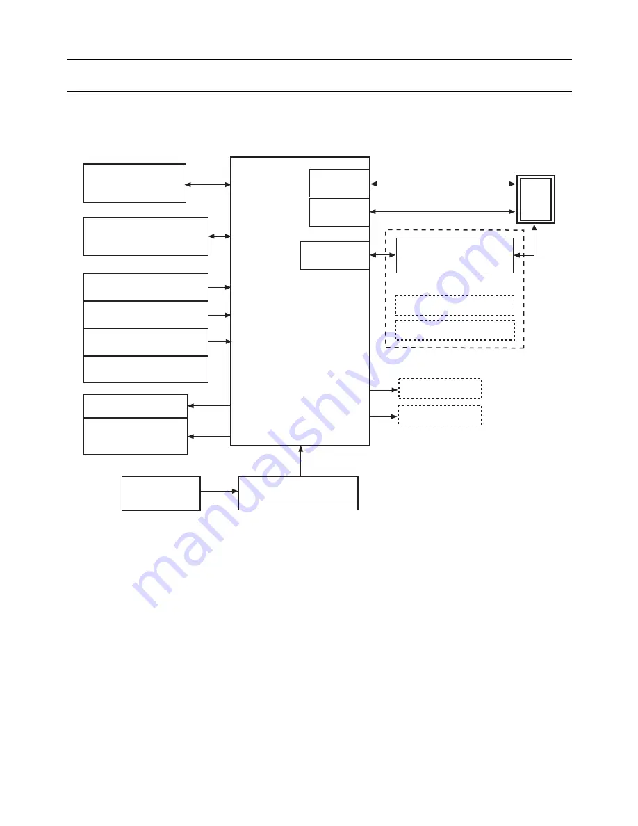
2-2-1. Configuration of Printer
The following shows major configuration blocks.
+5V, +24V
Head Up Sensor
Transparent Sensor
Reflective Sensor
Filter & Power Supply
[Power Supply PCB]
AC Inlet &
Power Switch
[Centro PCB]
Serial I/F
(USB)
Serial I/F
(RS-232C)
(Option)
Host
(PC)
PF Motor
Thermal Print Head
(Head Temp. Sensor)
Operation Panel
[Ope-pane PCB]
Cutter
Peeler
[Main PCB]
Parallel I/F
(IEEE1284)
Parallel I/F
Ethernet I/F PCB
Wireless LAN I/F PCB
(Option)
Ribbon Motor F/R
[Ribbon Main PCB]
Tension Sensor F/R
Major functions of individual components are described below:
(1) Filter & power supply section
Consists of a fuse, a filter circuit to eliminate external electric noise, and a switching type
regulator to transform an AC input to +5V DC and +24V DC outputs required to drive the
printer.
(2) Main PCB
Controls the entire operations of the printer. It consists of CPU, ROM, RAM, Custom IC, driver
circuits, etc.
(3) Operation panel
A panel used to indicate the operating status of the printer and to set specifications. It consists
of 4 keys and 4 LEDs.
Содержание CLP-621
Страница 1: ...Technical Manual CLP 621 CLP 631 Thermal Transfer Barcode Label Printer JM74961 00F 1 00E 0701...
Страница 2: ...CLP 621 CLP 631 ii Copyright 2007 by CITIZEN SYSTEMS JAPAN CO LTD...
Страница 4: ...CHAPTER 1 SPECIFICATIONS CLP 621 CLP 631...
Страница 13: ...CHAPTER 2 OPERATING PRINCIPLES CLP 621 CLP 631...
Страница 68: ...2 5 Power Supply CLP 621 CLP 631 2 56 N1 N2 N3 N4 BLOCK A BLOCK E BLOCK B BLOCK C BLOCK D 120V type...
Страница 69: ...2 5 Power Supply 2 57 CLP 621 CLP 631 N1 N2 N3 N4 Block A Block B Block C Block E Block D 220 240V type...
Страница 73: ...CHAPTER 3 DISASSEMBLY AND MAINTENANCE CLP 621 CLP 631...
Страница 126: ...CLP 621 CLP 631 CHAPTER 4 TROUBLESHOOTING...
Страница 138: ...CLP 621 CLP 631 CHAPTER 5 PARTS LISTS...
Страница 143: ...Chapter 5 Parts Lists CLP 621 CLP 631 5 6 DRAWING NO 1 General Assembly Rev 0 1 7 8 2 3 4 2 10 11 12 9 5 2 13 14 10...
Страница 163: ...Chapter 5 Parts Lists CLP 621 CLP 631 5 26 DRAWING NO 6 Sensor U Unit Rev 0 4 16 3 2 1 9 10 11 5 8 6 12 7 13 14 15...
Страница 166: ...Chapter 5 Parts Lists CLP 621 CLP 631 5 29 DRAWING NO 7 Control Panel Unit Rev 0 4 3 2 1 5...
Страница 174: ...Chapter 5 Parts Lists CLP 621 CLP 631 5 37 DRAWING NO 9 Ribbon Unit Fan SA2 Rev 0 1 2 4 3 5 6 3...
Страница 177: ...Chapter 5 Parts Lists CLP 621 CLP 631 5 40 DRAWING NO 10 Accessories Rev 0 3 2 4 1...
Страница 179: ...CHAPTER 6 CIRCUIT DIAGRAMS CLP 621 CLP 631...
Страница 208: ...APPENDICES CLP 621 CLP 631...
Страница 211: ...B Mounting Diagrams B Mounting Diagrams B Mounting Diagrams CLP 621 CLP 631 AP 4 AP 4 B 1 Main PCB Main PCB Parts side...
Страница 212: ...B Mounting Diagrams AP 5 CLP 621 CLP 631 Main PCB Solder side...
Страница 213: ...B Mounting Diagrams CLP 621 CLP 631 AP 6 AP 6 B 2 Power Supply PCB 120V 220V B 2 Power Supply PCB 120V 220V...
Страница 214: ...B Mounting Diagrams AP 7 CLP 621 CLP 631 B 3 Ribbon Main PCB Parts side Solder side...
Страница 217: ......


