


2-1. Operation of Each Mechanism
2-13
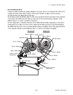
CLP-621 & CLP-631
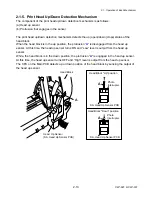
2-1-5. Print Head Up/Down Detection Mechanism
The component of the print head up/down detection mechanism is as follows:
(a) Head up sensor
(b) Protrusion that engages in the sensor
The print head up/down detection mechanism detects the up (open)/down (close) status of the
head block.
When the head block is in the up position, the protrusion “
A
” is disengaged from the head up
sensor. At this time, the head up sensor turns ON and “Low” level is output from the head up
sensor.
While, the head block is in the down position, the protrusion “
A
” is engaged in the head up sensor.
At this time, the head up sensor turns OFF and “High” level is output from the head up sensor.
The CPU on the Main PCB detects up or down position of the head block by sensing the output of
the head up sensor.
Head Up Sensor
(SA, Head Up Sensor PCB)
Head Block "Up" position
Head Block "Down" position
Head Block
SA, Head Up Sensor PCB
SA, Head Up Sensor PCB
Photo
Interrupter
Photo
Interrupter
A
A
A
Содержание CLP-621
Страница 1: ...Technical Manual CLP 621 CLP 631 Thermal Transfer Barcode Label Printer JM74961 00F 1 00E 0701...
Страница 2: ...CLP 621 CLP 631 ii Copyright 2007 by CITIZEN SYSTEMS JAPAN CO LTD...
Страница 4: ...CHAPTER 1 SPECIFICATIONS CLP 621 CLP 631...
Страница 13: ...CHAPTER 2 OPERATING PRINCIPLES CLP 621 CLP 631...
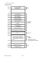
Страница 68: ...2 5 Power Supply CLP 621 CLP 631 2 56 N1 N2 N3 N4 BLOCK A BLOCK E BLOCK B BLOCK C BLOCK D 120V type...
Страница 69: ...2 5 Power Supply 2 57 CLP 621 CLP 631 N1 N2 N3 N4 Block A Block B Block C Block E Block D 220 240V type...
Страница 73: ...CHAPTER 3 DISASSEMBLY AND MAINTENANCE CLP 621 CLP 631...
Страница 126: ...CLP 621 CLP 631 CHAPTER 4 TROUBLESHOOTING...
Страница 138: ...CLP 621 CLP 631 CHAPTER 5 PARTS LISTS...
Страница 143: ...Chapter 5 Parts Lists CLP 621 CLP 631 5 6 DRAWING NO 1 General Assembly Rev 0 1 7 8 2 3 4 2 10 11 12 9 5 2 13 14 10...
Страница 163: ...Chapter 5 Parts Lists CLP 621 CLP 631 5 26 DRAWING NO 6 Sensor U Unit Rev 0 4 16 3 2 1 9 10 11 5 8 6 12 7 13 14 15...
Страница 166: ...Chapter 5 Parts Lists CLP 621 CLP 631 5 29 DRAWING NO 7 Control Panel Unit Rev 0 4 3 2 1 5...
Страница 174: ...Chapter 5 Parts Lists CLP 621 CLP 631 5 37 DRAWING NO 9 Ribbon Unit Fan SA2 Rev 0 1 2 4 3 5 6 3...
Страница 177: ...Chapter 5 Parts Lists CLP 621 CLP 631 5 40 DRAWING NO 10 Accessories Rev 0 3 2 4 1...
Страница 179: ...CHAPTER 6 CIRCUIT DIAGRAMS CLP 621 CLP 631...
Страница 208: ...APPENDICES CLP 621 CLP 631...
Страница 211: ...B Mounting Diagrams B Mounting Diagrams B Mounting Diagrams CLP 621 CLP 631 AP 4 AP 4 B 1 Main PCB Main PCB Parts side...
Страница 212: ...B Mounting Diagrams AP 5 CLP 621 CLP 631 Main PCB Solder side...
Страница 213: ...B Mounting Diagrams CLP 621 CLP 631 AP 6 AP 6 B 2 Power Supply PCB 120V 220V B 2 Power Supply PCB 120V 220V...
Страница 214: ...B Mounting Diagrams AP 7 CLP 621 CLP 631 B 3 Ribbon Main PCB Parts side Solder side...
Страница 217: ......


