


3-6. Adjustments
3-47
CLP-621 & CLP-631
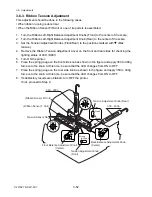
(2) Ribbon slant elimination adjustment (For service personnel)
(2-1) Tension base adjust cam position adjustment (For service personnel)
This adjustment is required in the following cases:
• If the parallelism reference for the user adjustable range needs to be changed. (This
adjustment will be required if ribbon wrinkle cannot be removed with the Ribbon
Left-Right Balance Adjustment Knobs (Front/Rear).)
• Tension Base Adjust Cam is replaced or reassembled.
By adjusting the Tension Base Adjust Cam, the parallelism of the Ribbon Sensor F/R Unit
(movable part) against the unit base (fixed part) is changed. The user adjustment using the
Left-Right Balance Adjustment Knobs (Front/Rear) is done based on the new parallelism
reference.
Note:
The Tension Base Adjust Cam is adjusted at the factory before shipping. Therefore,
it may be off-center when shipped.
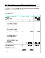
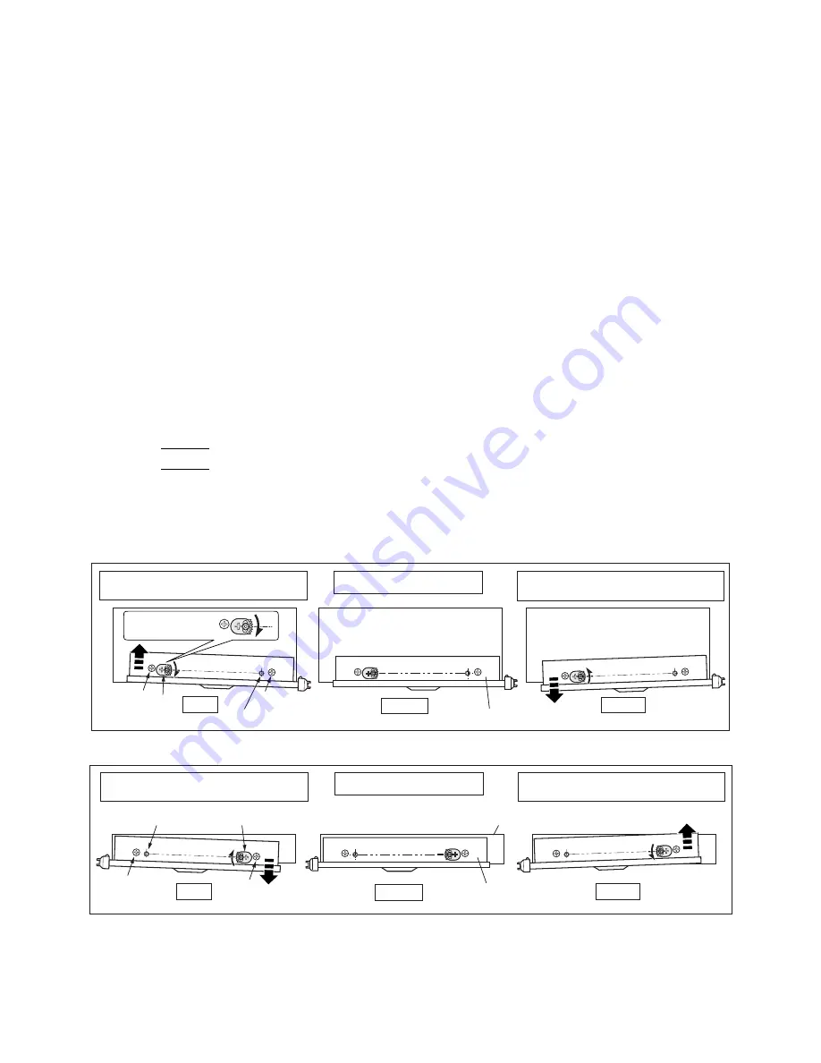
Adjustment procedure:
1. Remove the Ribbon Tension Adjustment Cover from the Ribbon Sensor F/R Unit.
2. Loosen 2 screws “
A
”.
3. Loosen the screw “
B
”, and turn the Tension Base Adjust Cam clockwise or
counterclockwise. The parallelism of the Ribbon Sensor F/R Unit against the base is
changed.
4. Tighten screws “
B
” and “
A
” (2 pcs.).
A B
Supporting point
Unit, Ribbon Sensor F
Shifting the Ribbon Sensor F Unit (Viewing from the front side)
Shifting the Ribbon Sensor R Unit (Viewing from the rear side)
B
CW
Supporting point
Unit, Ribbon Sensor F
Base
Center
CCW
CW
Center
CCW
Left side ribbon wrinkles cannot
be eliminated by user adjustment.
Mechanical center
Right side ribbon wrinkles cannot
be eliminated by user adjustment.
A
Left*
1
side ribbon wrinkles cannot
be eliminated by user adjustment.
Mechanical center
Right*
1
side ribbon wrinkles cannot
be eliminated by user adjustment.
A
A
*1: Shows the direction viewing from the rear side.
CW: Clockwise
CCW: Counterclockwise
Base
(SA1, Ribbon Unit Base Plate)
Cam, Base
Tension Adjust
Содержание CLP-621
Страница 1: ...Technical Manual CLP 621 CLP 631 Thermal Transfer Barcode Label Printer JM74961 00F 1 00E 0701...
Страница 2: ...CLP 621 CLP 631 ii Copyright 2007 by CITIZEN SYSTEMS JAPAN CO LTD...
Страница 4: ...CHAPTER 1 SPECIFICATIONS CLP 621 CLP 631...
Страница 13: ...CHAPTER 2 OPERATING PRINCIPLES CLP 621 CLP 631...
Страница 68: ...2 5 Power Supply CLP 621 CLP 631 2 56 N1 N2 N3 N4 BLOCK A BLOCK E BLOCK B BLOCK C BLOCK D 120V type...
Страница 69: ...2 5 Power Supply 2 57 CLP 621 CLP 631 N1 N2 N3 N4 Block A Block B Block C Block E Block D 220 240V type...
Страница 73: ...CHAPTER 3 DISASSEMBLY AND MAINTENANCE CLP 621 CLP 631...
Страница 126: ...CLP 621 CLP 631 CHAPTER 4 TROUBLESHOOTING...
Страница 138: ...CLP 621 CLP 631 CHAPTER 5 PARTS LISTS...
Страница 143: ...Chapter 5 Parts Lists CLP 621 CLP 631 5 6 DRAWING NO 1 General Assembly Rev 0 1 7 8 2 3 4 2 10 11 12 9 5 2 13 14 10...
Страница 163: ...Chapter 5 Parts Lists CLP 621 CLP 631 5 26 DRAWING NO 6 Sensor U Unit Rev 0 4 16 3 2 1 9 10 11 5 8 6 12 7 13 14 15...
Страница 166: ...Chapter 5 Parts Lists CLP 621 CLP 631 5 29 DRAWING NO 7 Control Panel Unit Rev 0 4 3 2 1 5...
Страница 174: ...Chapter 5 Parts Lists CLP 621 CLP 631 5 37 DRAWING NO 9 Ribbon Unit Fan SA2 Rev 0 1 2 4 3 5 6 3...
Страница 177: ...Chapter 5 Parts Lists CLP 621 CLP 631 5 40 DRAWING NO 10 Accessories Rev 0 3 2 4 1...
Страница 179: ...CHAPTER 6 CIRCUIT DIAGRAMS CLP 621 CLP 631...
Страница 208: ...APPENDICES CLP 621 CLP 631...
Страница 211: ...B Mounting Diagrams B Mounting Diagrams B Mounting Diagrams CLP 621 CLP 631 AP 4 AP 4 B 1 Main PCB Main PCB Parts side...
Страница 212: ...B Mounting Diagrams AP 5 CLP 621 CLP 631 Main PCB Solder side...
Страница 213: ...B Mounting Diagrams CLP 621 CLP 631 AP 6 AP 6 B 2 Power Supply PCB 120V 220V B 2 Power Supply PCB 120V 220V...
Страница 214: ...B Mounting Diagrams AP 7 CLP 621 CLP 631 B 3 Ribbon Main PCB Parts side Solder side...
Страница 217: ......


