


2-2. Operation of Control Parts
2-29
CLP-621 & CLP-631
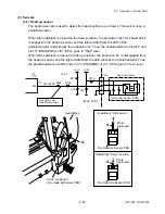
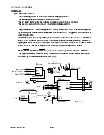
(4-2) Ribbon motor driver
This is a driving circuit to drive the Ribbon Motor F and Ribbon Motor R (stepping motors).
The Ribbon Motor F is used to take up ribbon and the Ribbon Motor R is used to supply
ribbon.
The Ribbon Motor F/R is driven by the STEP_A/B signal sent from the CPU (IC1). The
rotational direction of the motor is determined by the DIR_A/B signal sent from the custom
IC (IC11). The strength of PF motor excitation (strong and weak) is switched by the
PDOWN signal sent from the CPU (IC1).
The motor drive circuits for the Ribbon Motor F and Ribbon Motor R are the same except
that the latter circuit has the motor rotational direction change function.
On the supply side, it is required to change the motor rotational direction depending on the
ribbon to be used, inside wound (ink-in) ribbon or outside wound (ink-out) ribbon. The
output of the Ribbon Winding Selection Switch is connected to IC702, and, by combining
this output signal with the DIR_B signal, the rotational direction of the Ribbon Motor R is
changed.
5
11
20
VBB1
VBB2
DIR
STEP
IC701
Motor Driver
3
4
2
1
CN702
OUT1A
OUT1B
OUT2A
OUT2B
M
Ribbon Motor F
(Take-up Side)
21
16
4
9
IC12B
Monostable
Multivibrator
2CLR
2A
9
10
2B
11
2Q
5
From IC1 CPU
RIBTRG
GRESET
SN74LV123APWR
REF
C705
R709
PDOWN
[Main PCB]
1
10
DTR701
DTC143EUA
R706
R704
VR701
11
12
13
14
CN701
15
16
3
4
2
1
CN703
M
Ribbon Motor R
(Supply Side)
(Same as above circuit)
DIR_A
STEP_A
DIR_B
STEP_B
CN706
Inside Wound
Outside Wound
Ribbon Winding
Selection Switch
R733
1
2
7
DIR
STEP
PDOWN
PDOWN
DIR
STEP
VMOTON
IC11
Custom IC
PM0
95
IC1
CPU
D24
122
96
PM1
126
123
D28
D25
DIR SW
3
4
5
6
7
8
CN8
[Ribbon Main PCB]
[DIR SW PCB]
4
5
PDOWN
DIR_A
STEP_A
DIR_B
STEP_B
IC702
IC706
DTR703
DTC143EUA
TR701
T703
VMOTON
+24V
R724
R725
+3.3V
F701
2SJ358
Содержание CLP-621
Страница 1: ...Technical Manual CLP 621 CLP 631 Thermal Transfer Barcode Label Printer JM74961 00F 1 00E 0701...
Страница 2: ...CLP 621 CLP 631 ii Copyright 2007 by CITIZEN SYSTEMS JAPAN CO LTD...
Страница 4: ...CHAPTER 1 SPECIFICATIONS CLP 621 CLP 631...
Страница 13: ...CHAPTER 2 OPERATING PRINCIPLES CLP 621 CLP 631...
Страница 68: ...2 5 Power Supply CLP 621 CLP 631 2 56 N1 N2 N3 N4 BLOCK A BLOCK E BLOCK B BLOCK C BLOCK D 120V type...
Страница 69: ...2 5 Power Supply 2 57 CLP 621 CLP 631 N1 N2 N3 N4 Block A Block B Block C Block E Block D 220 240V type...
Страница 73: ...CHAPTER 3 DISASSEMBLY AND MAINTENANCE CLP 621 CLP 631...
Страница 126: ...CLP 621 CLP 631 CHAPTER 4 TROUBLESHOOTING...
Страница 138: ...CLP 621 CLP 631 CHAPTER 5 PARTS LISTS...
Страница 143: ...Chapter 5 Parts Lists CLP 621 CLP 631 5 6 DRAWING NO 1 General Assembly Rev 0 1 7 8 2 3 4 2 10 11 12 9 5 2 13 14 10...
Страница 163: ...Chapter 5 Parts Lists CLP 621 CLP 631 5 26 DRAWING NO 6 Sensor U Unit Rev 0 4 16 3 2 1 9 10 11 5 8 6 12 7 13 14 15...
Страница 166: ...Chapter 5 Parts Lists CLP 621 CLP 631 5 29 DRAWING NO 7 Control Panel Unit Rev 0 4 3 2 1 5...
Страница 174: ...Chapter 5 Parts Lists CLP 621 CLP 631 5 37 DRAWING NO 9 Ribbon Unit Fan SA2 Rev 0 1 2 4 3 5 6 3...
Страница 177: ...Chapter 5 Parts Lists CLP 621 CLP 631 5 40 DRAWING NO 10 Accessories Rev 0 3 2 4 1...
Страница 179: ...CHAPTER 6 CIRCUIT DIAGRAMS CLP 621 CLP 631...
Страница 208: ...APPENDICES CLP 621 CLP 631...
Страница 211: ...B Mounting Diagrams B Mounting Diagrams B Mounting Diagrams CLP 621 CLP 631 AP 4 AP 4 B 1 Main PCB Main PCB Parts side...
Страница 212: ...B Mounting Diagrams AP 5 CLP 621 CLP 631 Main PCB Solder side...
Страница 213: ...B Mounting Diagrams CLP 621 CLP 631 AP 6 AP 6 B 2 Power Supply PCB 120V 220V B 2 Power Supply PCB 120V 220V...
Страница 214: ...B Mounting Diagrams AP 7 CLP 621 CLP 631 B 3 Ribbon Main PCB Parts side Solder side...
Страница 217: ......


