


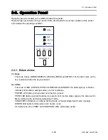


2-3. Operation Panel
CLP-621 & CLP-631
2-44
(3-3) Factory/Service Mode menu table
The following table shows the value and description of each submenu under Factory Mode
menu and Service Mode menu.
(a) Factory Mode menu table
*:
“+” shows that the object logically moves forward/rightward. “-“ shows that the
object logically moves backward/leftward.
**: For both CLP-621 and CLP-631, 8 dots correspond to 1 mm for each adjustment value.
(Namely, 203 dots correspond to 1”.)
Submenu Name
Adjustable Value
(Default Value)
Description
Through Sensor
Position
(See
Note 1
.)
-256 to +256 [dots]
(+000 [dots])
Logically shifts the transparent sensor position
back and forth. (-32 to +32 mm, -1.26 to +1.26”)
Reflect Sensor
Position
(See
Note 1
.)
-256 to +256 [dots]
(+000 [dots])
Logically shifts the reflective sensor position back
and forth. (-32 to +32 mm, -1.26 to +1.26”)
Machine Tear
Position
-256 to +256 [dots]
(+000 [dots])
Logically shifts the tear off position back and forth.
(-32 to +32 mm, -1.26 to +1.26”)
Machine Cut
Position
-256 to +256 [dots]
(+000 [dots])
Logically shifts the cutting position back and forth.
(-32 to +32 mm, -1.26 to +1.26”) (Optional)
Machine Peel
Position
-256 to +256 [dots]
(+000 [dots])
Logically shifts the peel position back and forth.
(-32 to +32 mm, -1.26 to +1.26”) (Optional)
Machine
Horizontal Pos.
-16 to +32 [dots]
(+08 [dots])
Logically shifts the head position to the right or left
side.
(-2 to +4 mm, -0.08 to +0.16”)
AutoCal Mode
ON, OFF
(ON)
Automatically controls the light amount in each
Media sensor menu (See Through, Reflect, None).
See Through
Sensor
0.0 to 3.3 [V]
(0.0 [V])
This menu is effective when “AutoCal Mode” is set
to OFF. The light amount in Media sensor menu
“See Through” can be changed manually.
Larger value emits larger amount of light.
Reflect Sensor
0.0 to 3.3 [V]
(0.0 [V])
This menu is effective when “AutoCal Mode” is set
to OFF. The light amount in Media Sensor menu
“Reflect” can be changed manually.
Larger value emits larger amount of light.
Note 1
:
“Through Sensor Position” adjustment and “Reflect Sensor Position” adjustment must be
done if one of the following parts is replaced.
• Main PCB Unit
• Transparent Sensor PCB SA
• Reflective Sensor PCB SA
Содержание CLP-621
Страница 1: ...Technical Manual CLP 621 CLP 631 Thermal Transfer Barcode Label Printer JM74961 00F 1 00E 0701...
Страница 2: ...CLP 621 CLP 631 ii Copyright 2007 by CITIZEN SYSTEMS JAPAN CO LTD...
Страница 4: ...CHAPTER 1 SPECIFICATIONS CLP 621 CLP 631...
Страница 13: ...CHAPTER 2 OPERATING PRINCIPLES CLP 621 CLP 631...
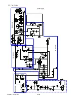
Страница 68: ...2 5 Power Supply CLP 621 CLP 631 2 56 N1 N2 N3 N4 BLOCK A BLOCK E BLOCK B BLOCK C BLOCK D 120V type...
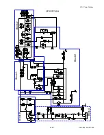
Страница 69: ...2 5 Power Supply 2 57 CLP 621 CLP 631 N1 N2 N3 N4 Block A Block B Block C Block E Block D 220 240V type...
Страница 73: ...CHAPTER 3 DISASSEMBLY AND MAINTENANCE CLP 621 CLP 631...
Страница 126: ...CLP 621 CLP 631 CHAPTER 4 TROUBLESHOOTING...
Страница 138: ...CLP 621 CLP 631 CHAPTER 5 PARTS LISTS...
Страница 143: ...Chapter 5 Parts Lists CLP 621 CLP 631 5 6 DRAWING NO 1 General Assembly Rev 0 1 7 8 2 3 4 2 10 11 12 9 5 2 13 14 10...
Страница 163: ...Chapter 5 Parts Lists CLP 621 CLP 631 5 26 DRAWING NO 6 Sensor U Unit Rev 0 4 16 3 2 1 9 10 11 5 8 6 12 7 13 14 15...
Страница 166: ...Chapter 5 Parts Lists CLP 621 CLP 631 5 29 DRAWING NO 7 Control Panel Unit Rev 0 4 3 2 1 5...
Страница 174: ...Chapter 5 Parts Lists CLP 621 CLP 631 5 37 DRAWING NO 9 Ribbon Unit Fan SA2 Rev 0 1 2 4 3 5 6 3...
Страница 177: ...Chapter 5 Parts Lists CLP 621 CLP 631 5 40 DRAWING NO 10 Accessories Rev 0 3 2 4 1...
Страница 179: ...CHAPTER 6 CIRCUIT DIAGRAMS CLP 621 CLP 631...
Страница 208: ...APPENDICES CLP 621 CLP 631...
Страница 211: ...B Mounting Diagrams B Mounting Diagrams B Mounting Diagrams CLP 621 CLP 631 AP 4 AP 4 B 1 Main PCB Main PCB Parts side...
Страница 212: ...B Mounting Diagrams AP 5 CLP 621 CLP 631 Main PCB Solder side...
Страница 213: ...B Mounting Diagrams CLP 621 CLP 631 AP 6 AP 6 B 2 Power Supply PCB 120V 220V B 2 Power Supply PCB 120V 220V...
Страница 214: ...B Mounting Diagrams AP 7 CLP 621 CLP 631 B 3 Ribbon Main PCB Parts side Solder side...
Страница 217: ......


