


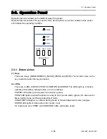


2-3. Operation Panel
CLP-621 & CLP-631
2-46
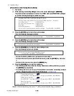
How to change the value in the Factory Mode menu
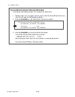
For example, the following shows how to logically move the thermal head position 1 mm
(0.04”) to the right. In this case, you should add 8 (dots) to the current value (e.g. +08).
• Variable range: -16 to +32 dots (d08 dots) (-2 to +4 mm, -0.08 to +0.16 mm”)
• 8 dots correspond to 1 mm. (203 dots correspond to 1”.)
1. Perform steps 1 to 6 on page
to enter the Factory Mode menu. See (b) “How to
enter the Factory/Service Mode”.
2. Press
the
[PAUSE]
key until “Mach Hor Pos” submenu is printed.
Note:
In the actual printing, the cursor “^” will be printed instead of “ (underline)”.
3. To set the value to 16 (8 plus 8), press the
[FEED]
key to move the cursor to the next
digit (+08), and then press the
[STOP]
key once to specify “1”.
Each time you press the key, the value of the current digit with the cursor will scroll (0,
1, 2, 3, 4, ...., 9, 0).
4. Next, press the
[FEED]
key to move the cursor to the next digit (+18).
The changed value is printed.
5. Press
the
[STOP]
key 8 times to specify “6”.
Each time you press the key, the value will scroll (8, 9, 0, 1, ...., 6).
6. To save the set value, press the
[PAUSE]
key.
The set value will be printed. Be sure that the new value is “16”, and then press the
[MODE]
key to exit the item.
* If the value is not the one you expected, repeat above operation.
Do you want to change “Factory Mode Menu” items?
Y
es=(PAUSE) No=(STOP) Exit=(MODE)
Through Sensor Position
+000
Save=(PAUSE) Next Digit=(FEED) Change value=(STOP) Exit=(MODE)
:
:
Mach Hor Pos
+08
Save=(PAUSE) Next Digit=(FEED) Change value=(STOP) Exit=(MODE)
Mach Hor Pos
+18
Save=(PAUSE) Next Digit=(FEED) Change value=(STOP) Exit=(MODE)
Mach Hor Pos
+16
Save=(PAUSE) Next Digit=(FEED) Change value=(STOP) Exit=(MODE)
1 mm
[Front]
Head
+
Содержание CLP-621
Страница 1: ...Technical Manual CLP 621 CLP 631 Thermal Transfer Barcode Label Printer JM74961 00F 1 00E 0701...
Страница 2: ...CLP 621 CLP 631 ii Copyright 2007 by CITIZEN SYSTEMS JAPAN CO LTD...
Страница 4: ...CHAPTER 1 SPECIFICATIONS CLP 621 CLP 631...
Страница 13: ...CHAPTER 2 OPERATING PRINCIPLES CLP 621 CLP 631...
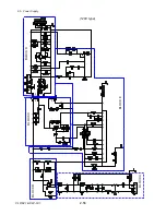
Страница 68: ...2 5 Power Supply CLP 621 CLP 631 2 56 N1 N2 N3 N4 BLOCK A BLOCK E BLOCK B BLOCK C BLOCK D 120V type...
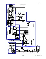
Страница 69: ...2 5 Power Supply 2 57 CLP 621 CLP 631 N1 N2 N3 N4 Block A Block B Block C Block E Block D 220 240V type...
Страница 73: ...CHAPTER 3 DISASSEMBLY AND MAINTENANCE CLP 621 CLP 631...
Страница 126: ...CLP 621 CLP 631 CHAPTER 4 TROUBLESHOOTING...
Страница 138: ...CLP 621 CLP 631 CHAPTER 5 PARTS LISTS...
Страница 143: ...Chapter 5 Parts Lists CLP 621 CLP 631 5 6 DRAWING NO 1 General Assembly Rev 0 1 7 8 2 3 4 2 10 11 12 9 5 2 13 14 10...
Страница 163: ...Chapter 5 Parts Lists CLP 621 CLP 631 5 26 DRAWING NO 6 Sensor U Unit Rev 0 4 16 3 2 1 9 10 11 5 8 6 12 7 13 14 15...
Страница 166: ...Chapter 5 Parts Lists CLP 621 CLP 631 5 29 DRAWING NO 7 Control Panel Unit Rev 0 4 3 2 1 5...
Страница 174: ...Chapter 5 Parts Lists CLP 621 CLP 631 5 37 DRAWING NO 9 Ribbon Unit Fan SA2 Rev 0 1 2 4 3 5 6 3...
Страница 177: ...Chapter 5 Parts Lists CLP 621 CLP 631 5 40 DRAWING NO 10 Accessories Rev 0 3 2 4 1...
Страница 179: ...CHAPTER 6 CIRCUIT DIAGRAMS CLP 621 CLP 631...
Страница 208: ...APPENDICES CLP 621 CLP 631...
Страница 211: ...B Mounting Diagrams B Mounting Diagrams B Mounting Diagrams CLP 621 CLP 631 AP 4 AP 4 B 1 Main PCB Main PCB Parts side...
Страница 212: ...B Mounting Diagrams AP 5 CLP 621 CLP 631 Main PCB Solder side...
Страница 213: ...B Mounting Diagrams CLP 621 CLP 631 AP 6 AP 6 B 2 Power Supply PCB 120V 220V B 2 Power Supply PCB 120V 220V...
Страница 214: ...B Mounting Diagrams AP 7 CLP 621 CLP 631 B 3 Ribbon Main PCB Parts side Solder side...
Страница 217: ......


