


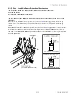


2-2. Operation of Control Parts
2-19
CLP-621 & CLP-631
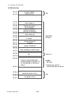
(a) CPU
The CPU is a microprocessor with 32-bit architecture. The clock fed to the CPU is 16 MHz.
The CPU internally multiplies this 16 MHz by 8 times and uses 128 MHz clock. The CPU
includes cache memory, RAMs, DMA controller, serial I/F, USB function controller, A/D
converter, etc.
(b) Flash ROM
A flash ROM of 16M bits (2M bytes) that stores the firmware and CG (character generator)
(c) SDRAM (Synchronous dynamic RAM)
A SDRAM of 64M bits (8M bytes) that is used as working area, input buffer and download
buffer
(d) Custom IC
The custom IC incorporates a control circuit for the interface I/O port, motors, print head,
etc.
(e) Head control
This is a circuit to control the thermal head driver incorporated in the thermal head. It also
checks if a thermal element of the thermal head is faulty.
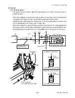
(f) PF motor driver
This is a circuit to drive the PF Motor. The PF Motor is a stepping motor.
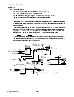
(g) Ribbon motor driver
This is a circuit to drive the Ribbon Motor F and Ribbon Motor R. These motors are
stepping motors. The rotational direction of the Ribbon Motor R is changed by the setting
of the Ribbon Winding Selection Switch.
(
h
) Buzzer
The buzzer is driven when an alarm, etc. occurs.
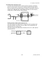
(i) Fan
Cooling fan for the ribbon motor. When the temperature of the Ribbon Motor F (take-up
side motor) exceeds a certain value, this fan starts to work.
Содержание CLP-621
Страница 1: ...Technical Manual CLP 621 CLP 631 Thermal Transfer Barcode Label Printer JM74961 00F 1 00E 0701...
Страница 2: ...CLP 621 CLP 631 ii Copyright 2007 by CITIZEN SYSTEMS JAPAN CO LTD...
Страница 4: ...CHAPTER 1 SPECIFICATIONS CLP 621 CLP 631...
Страница 13: ...CHAPTER 2 OPERATING PRINCIPLES CLP 621 CLP 631...
Страница 68: ...2 5 Power Supply CLP 621 CLP 631 2 56 N1 N2 N3 N4 BLOCK A BLOCK E BLOCK B BLOCK C BLOCK D 120V type...
Страница 69: ...2 5 Power Supply 2 57 CLP 621 CLP 631 N1 N2 N3 N4 Block A Block B Block C Block E Block D 220 240V type...
Страница 73: ...CHAPTER 3 DISASSEMBLY AND MAINTENANCE CLP 621 CLP 631...
Страница 126: ...CLP 621 CLP 631 CHAPTER 4 TROUBLESHOOTING...
Страница 138: ...CLP 621 CLP 631 CHAPTER 5 PARTS LISTS...
Страница 143: ...Chapter 5 Parts Lists CLP 621 CLP 631 5 6 DRAWING NO 1 General Assembly Rev 0 1 7 8 2 3 4 2 10 11 12 9 5 2 13 14 10...
Страница 163: ...Chapter 5 Parts Lists CLP 621 CLP 631 5 26 DRAWING NO 6 Sensor U Unit Rev 0 4 16 3 2 1 9 10 11 5 8 6 12 7 13 14 15...
Страница 166: ...Chapter 5 Parts Lists CLP 621 CLP 631 5 29 DRAWING NO 7 Control Panel Unit Rev 0 4 3 2 1 5...
Страница 174: ...Chapter 5 Parts Lists CLP 621 CLP 631 5 37 DRAWING NO 9 Ribbon Unit Fan SA2 Rev 0 1 2 4 3 5 6 3...
Страница 177: ...Chapter 5 Parts Lists CLP 621 CLP 631 5 40 DRAWING NO 10 Accessories Rev 0 3 2 4 1...
Страница 179: ...CHAPTER 6 CIRCUIT DIAGRAMS CLP 621 CLP 631...
Страница 208: ...APPENDICES CLP 621 CLP 631...
Страница 211: ...B Mounting Diagrams B Mounting Diagrams B Mounting Diagrams CLP 621 CLP 631 AP 4 AP 4 B 1 Main PCB Main PCB Parts side...
Страница 212: ...B Mounting Diagrams AP 5 CLP 621 CLP 631 Main PCB Solder side...
Страница 213: ...B Mounting Diagrams CLP 621 CLP 631 AP 6 AP 6 B 2 Power Supply PCB 120V 220V B 2 Power Supply PCB 120V 220V...
Страница 214: ...B Mounting Diagrams AP 7 CLP 621 CLP 631 B 3 Ribbon Main PCB Parts side Solder side...
Страница 217: ......


