


2-2. Operation of Control Parts
trol Parts
CLP-621 & CLP-631
2-30
CLP-621 & CLP-631
2-30
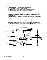
(4-3) Head driver
(4-3) Head driver
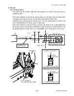
The head driver is incorporated in the Head SA.
The head driver is incorporated in the Head SA.
When printing, pin 116 (HDVON) of IC11 (Custom IC) goes to "High" level, and DTR1 and
TR1 turn ON. Thus +24V is supplied to the thermal head (Head SA).
When printing, pin 116 (HDVON) of IC11 (Custom IC) goes to "High" level, and DTR1 and
TR1 turn ON. Thus +24V is supplied to the thermal head (Head SA).
The print data is sent from the Custom IC (IC11) to the head driver to select the thermal
elements to be heated. The data is sent via HD1 to 3, HDSTB, HDCLK and HDLAT lines
(pins 110, 111, 113, 108, 115 and 107 of IC11).
The print data is sent from the Custom IC (IC11) to the head driver to select the thermal
elements to be heated. The data is sent via HD1 to 3, HDSTB, HDCLK and HDLAT lines
(pins 110, 111, 113, 108, 115 and 107 of IC11).
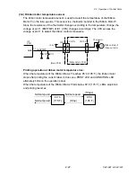
According to the print data, the thermal head heats the thermal elements to print dots on
thermal transfer paper. The width of heating pulse will be changed according to the head
temperature to keep the printing density constant.
According to the print data, the thermal head heats the thermal elements to print dots on
thermal transfer paper. The width of heating pulse will be changed according to the head
temperature to keep the printing density constant.
CN4
Thermal
Head
5,6,8,11,12
20,22
1-4,23-26
HDSTB1-3
HDCLK
HDDAT1-3
HDLAT
+3.3V
VHEAD
10,14,17
19
P174-
176
P177
P178
P179
IC11
Custom IC
HDLTH
107
HDSTB
108
HDCLK
115
HDATA1-3
110,
111,
113
HDVON
HCVON
HDVON
116
HCVON
117
+24V
R76
R77
TR1
DTR1
+5V
R81
R82
DTR2
R84
VHEAD
DTC143EUA
DTC143EUA
P170
D2
2SJ553S
TR2
2SJ647
D1
+3.3V
IC1
CPU
D3
+3.3V
R83
R78
R80
R79
P166
P171
P173
P164
Head supply voltage ON/OFF
Thermal element abnormality check ON
Head power supply monitor
Thermal element abnormality check
[Main PCB]
When driving: +24V
When checking: +5V
HD1-3
HDSTB
HDCLK
HDLAT
7
5
6
2-3
13
15
14
16-18
16
18
7,9,15
174
PRT_MODE
IC1
CPU
P74
Fixed to L.
+3.3V
R159
HDTHM1
P167
P162
P172
P168
VHEADMON
HEADRES
P169
P163
ANI4
9
ANI5
10
A1-3
B1-3
A4
B4
A5
B5
A6
B6
IC21A
27
Содержание CLP-621
Страница 1: ...Technical Manual CLP 621 CLP 631 Thermal Transfer Barcode Label Printer JM74961 00F 1 00E 0701...
Страница 2: ...CLP 621 CLP 631 ii Copyright 2007 by CITIZEN SYSTEMS JAPAN CO LTD...
Страница 4: ...CHAPTER 1 SPECIFICATIONS CLP 621 CLP 631...
Страница 13: ...CHAPTER 2 OPERATING PRINCIPLES CLP 621 CLP 631...
Страница 68: ...2 5 Power Supply CLP 621 CLP 631 2 56 N1 N2 N3 N4 BLOCK A BLOCK E BLOCK B BLOCK C BLOCK D 120V type...
Страница 69: ...2 5 Power Supply 2 57 CLP 621 CLP 631 N1 N2 N3 N4 Block A Block B Block C Block E Block D 220 240V type...
Страница 73: ...CHAPTER 3 DISASSEMBLY AND MAINTENANCE CLP 621 CLP 631...
Страница 126: ...CLP 621 CLP 631 CHAPTER 4 TROUBLESHOOTING...
Страница 138: ...CLP 621 CLP 631 CHAPTER 5 PARTS LISTS...
Страница 143: ...Chapter 5 Parts Lists CLP 621 CLP 631 5 6 DRAWING NO 1 General Assembly Rev 0 1 7 8 2 3 4 2 10 11 12 9 5 2 13 14 10...
Страница 163: ...Chapter 5 Parts Lists CLP 621 CLP 631 5 26 DRAWING NO 6 Sensor U Unit Rev 0 4 16 3 2 1 9 10 11 5 8 6 12 7 13 14 15...
Страница 166: ...Chapter 5 Parts Lists CLP 621 CLP 631 5 29 DRAWING NO 7 Control Panel Unit Rev 0 4 3 2 1 5...
Страница 174: ...Chapter 5 Parts Lists CLP 621 CLP 631 5 37 DRAWING NO 9 Ribbon Unit Fan SA2 Rev 0 1 2 4 3 5 6 3...
Страница 177: ...Chapter 5 Parts Lists CLP 621 CLP 631 5 40 DRAWING NO 10 Accessories Rev 0 3 2 4 1...
Страница 179: ...CHAPTER 6 CIRCUIT DIAGRAMS CLP 621 CLP 631...
Страница 208: ...APPENDICES CLP 621 CLP 631...
Страница 211: ...B Mounting Diagrams B Mounting Diagrams B Mounting Diagrams CLP 621 CLP 631 AP 4 AP 4 B 1 Main PCB Main PCB Parts side...
Страница 212: ...B Mounting Diagrams AP 5 CLP 621 CLP 631 Main PCB Solder side...
Страница 213: ...B Mounting Diagrams CLP 621 CLP 631 AP 6 AP 6 B 2 Power Supply PCB 120V 220V B 2 Power Supply PCB 120V 220V...
Страница 214: ...B Mounting Diagrams AP 7 CLP 621 CLP 631 B 3 Ribbon Main PCB Parts side Solder side...
Страница 217: ......


