


4-2. Troubleshooting
4-9
CLP-621 & CLP-631
Symptoms
Checks
Remedies
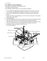
Ribbon slants.
1. Is the ribbon correctly inserted into the
ribbon holders?
2. Is the ribbon path correct?
3. Is the ribbon slant elimination
adjustment made?
1. Insert the ribbon correctly.
2. Install the ribbon correctly.
3. Adjust it according to 3-6-2 “Ribbon
Slant Elimination Adjustment”.
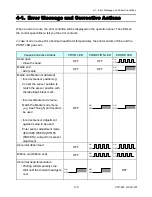
4-2-5. Sensor Problems
Symptoms
Checks
Remedies
Head block is closed,
but head open error
is indicated by LEDs.
(Head up sensor
problem)
1.
Is the Head Up Sensor Cable SA firmly
connected between the Head Up
Sensor PCB SA and the Main PCB SA
(CN9)?
2. Is the protrusion (metal end) inserted
into the photointerrupter of the Head Up
Sensor PCB SA?
3.
Failure in the control circuit.
1. Connect it firmly.
2. Replace the Head Up Sensor PCB
SA.
3. Replace the Main PCB Unit.
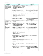
Ribbon tension is not
correctly controlled.
(Tension sensor F/R
problem)
1.
Is the cable firmly connected between
the Sensor Tension SA on the take-up
side and the Ribbon Main PCB SA
(CN704)?
2.
Is the cable firmly connected between
the Sensor Tension SA on the supply
side and the Ribbon Main PCB SA
(CN705)?
3.
Is the tension value in the specified
range?
4.
Does the ribbon sensor F/R work
correctly?
Remove the ribbon, and push and
release the Ribbon Senor F/R Unit with
your finger tip to see if the LED of the
Tension Senor SA turns ON and OFF.
(Remove the Ribbon Tension
Adjustment Cover to see LED.)
5.
Failure in the control circuit.
1. Connect it firmly.
2. Connect it firmly.
3. Adjust tension according to 3-6-3
“Ribbon Tension Adjustment”.
4. Replace the Tension Sensor SA on
the take-up/supply side.
For the location of LED, see 3-6-3
“Ribbon Tension Adjustment”.
5. Replace the Ribbon Main PCB SA
or the Main PCB Unit.
Содержание CLP-621
Страница 1: ...Technical Manual CLP 621 CLP 631 Thermal Transfer Barcode Label Printer JM74961 00F 1 00E 0701...
Страница 2: ...CLP 621 CLP 631 ii Copyright 2007 by CITIZEN SYSTEMS JAPAN CO LTD...
Страница 4: ...CHAPTER 1 SPECIFICATIONS CLP 621 CLP 631...
Страница 13: ...CHAPTER 2 OPERATING PRINCIPLES CLP 621 CLP 631...
Страница 68: ...2 5 Power Supply CLP 621 CLP 631 2 56 N1 N2 N3 N4 BLOCK A BLOCK E BLOCK B BLOCK C BLOCK D 120V type...
Страница 69: ...2 5 Power Supply 2 57 CLP 621 CLP 631 N1 N2 N3 N4 Block A Block B Block C Block E Block D 220 240V type...
Страница 73: ...CHAPTER 3 DISASSEMBLY AND MAINTENANCE CLP 621 CLP 631...
Страница 126: ...CLP 621 CLP 631 CHAPTER 4 TROUBLESHOOTING...
Страница 138: ...CLP 621 CLP 631 CHAPTER 5 PARTS LISTS...
Страница 143: ...Chapter 5 Parts Lists CLP 621 CLP 631 5 6 DRAWING NO 1 General Assembly Rev 0 1 7 8 2 3 4 2 10 11 12 9 5 2 13 14 10...
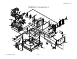
Страница 163: ...Chapter 5 Parts Lists CLP 621 CLP 631 5 26 DRAWING NO 6 Sensor U Unit Rev 0 4 16 3 2 1 9 10 11 5 8 6 12 7 13 14 15...
Страница 166: ...Chapter 5 Parts Lists CLP 621 CLP 631 5 29 DRAWING NO 7 Control Panel Unit Rev 0 4 3 2 1 5...
Страница 174: ...Chapter 5 Parts Lists CLP 621 CLP 631 5 37 DRAWING NO 9 Ribbon Unit Fan SA2 Rev 0 1 2 4 3 5 6 3...
Страница 177: ...Chapter 5 Parts Lists CLP 621 CLP 631 5 40 DRAWING NO 10 Accessories Rev 0 3 2 4 1...
Страница 179: ...CHAPTER 6 CIRCUIT DIAGRAMS CLP 621 CLP 631...
Страница 208: ...APPENDICES CLP 621 CLP 631...
Страница 211: ...B Mounting Diagrams B Mounting Diagrams B Mounting Diagrams CLP 621 CLP 631 AP 4 AP 4 B 1 Main PCB Main PCB Parts side...
Страница 212: ...B Mounting Diagrams AP 5 CLP 621 CLP 631 Main PCB Solder side...
Страница 213: ...B Mounting Diagrams CLP 621 CLP 631 AP 6 AP 6 B 2 Power Supply PCB 120V 220V B 2 Power Supply PCB 120V 220V...
Страница 214: ...B Mounting Diagrams AP 7 CLP 621 CLP 631 B 3 Ribbon Main PCB Parts side Solder side...
Страница 217: ......


