


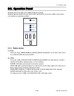


2-3. Operation Panel
2-39
CLP-621 & CLP-631
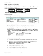
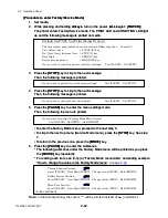
(2-2) Hex dump mode
(2-2) Hex dump mode
You can print the data in the receive buffer in the hexadecimal form.
You can print the data in the receive buffer in the hexadecimal form.
For label:
For label:
1. While pressing and holding the
[STOP]
key, turn on the power.
1. While pressing and holding the
[STOP]
key, turn on the power.
2. When the PRINT LED blinks slowly
2. When the PRINT LED blinks slowly (later, it will blink rapidly), release the
[STOP]
key.
The printer enters hex dump mode and hex dump printing starts.
To exit hex dump mode, turn off the power.
For continuous media:
1. While pressing and holding the
[STOP]
key, turn on the power.
2. The PRINT LED will blink slowly. When it changes to rapid blink, release the
[STOP]
key.
The printer enters hex dump mode and hex dump printing starts.
To exit hex dump mode, turn off the power.
DUMP LIST
02 40 30 31 30 30 0D 02 60 30 30 32 30 0D 02 4C .M0100..c0020..L
44 31 31 0D 31 30 30 30 30 30 30 30 30 30 31 30 D11.100000000010
30 30 31 30 31 32 33 34 35 36 37 38 39 3A 3B 3C 0010123456789:;<
[Dump list example]
(3) Factory/Service mode
Operation
Description
Remarks
All keys + [POWER]
Enters factory mode and service mode
(3-1) General
Factory mode and Service mode are available for maintenance.
Factory mode:
You can change the factory-set items such as logical shift of the sensor or head, and
double heat (printing the same dot twice).
Note:
y
In Factory mode, DO NOT change the factory-set values unless you need it, since
there are essential items related to printing accuracy, etc.
Содержание CLP-621
Страница 1: ...Technical Manual CLP 621 CLP 631 Thermal Transfer Barcode Label Printer JM74961 00F 1 00E 0701...
Страница 2: ...CLP 621 CLP 631 ii Copyright 2007 by CITIZEN SYSTEMS JAPAN CO LTD...
Страница 4: ...CHAPTER 1 SPECIFICATIONS CLP 621 CLP 631...
Страница 13: ...CHAPTER 2 OPERATING PRINCIPLES CLP 621 CLP 631...
Страница 68: ...2 5 Power Supply CLP 621 CLP 631 2 56 N1 N2 N3 N4 BLOCK A BLOCK E BLOCK B BLOCK C BLOCK D 120V type...
Страница 69: ...2 5 Power Supply 2 57 CLP 621 CLP 631 N1 N2 N3 N4 Block A Block B Block C Block E Block D 220 240V type...
Страница 73: ...CHAPTER 3 DISASSEMBLY AND MAINTENANCE CLP 621 CLP 631...
Страница 126: ...CLP 621 CLP 631 CHAPTER 4 TROUBLESHOOTING...
Страница 138: ...CLP 621 CLP 631 CHAPTER 5 PARTS LISTS...
Страница 143: ...Chapter 5 Parts Lists CLP 621 CLP 631 5 6 DRAWING NO 1 General Assembly Rev 0 1 7 8 2 3 4 2 10 11 12 9 5 2 13 14 10...
Страница 163: ...Chapter 5 Parts Lists CLP 621 CLP 631 5 26 DRAWING NO 6 Sensor U Unit Rev 0 4 16 3 2 1 9 10 11 5 8 6 12 7 13 14 15...
Страница 166: ...Chapter 5 Parts Lists CLP 621 CLP 631 5 29 DRAWING NO 7 Control Panel Unit Rev 0 4 3 2 1 5...
Страница 174: ...Chapter 5 Parts Lists CLP 621 CLP 631 5 37 DRAWING NO 9 Ribbon Unit Fan SA2 Rev 0 1 2 4 3 5 6 3...
Страница 177: ...Chapter 5 Parts Lists CLP 621 CLP 631 5 40 DRAWING NO 10 Accessories Rev 0 3 2 4 1...
Страница 179: ...CHAPTER 6 CIRCUIT DIAGRAMS CLP 621 CLP 631...
Страница 208: ...APPENDICES CLP 621 CLP 631...
Страница 211: ...B Mounting Diagrams B Mounting Diagrams B Mounting Diagrams CLP 621 CLP 631 AP 4 AP 4 B 1 Main PCB Main PCB Parts side...
Страница 212: ...B Mounting Diagrams AP 5 CLP 621 CLP 631 Main PCB Solder side...
Страница 213: ...B Mounting Diagrams CLP 621 CLP 631 AP 6 AP 6 B 2 Power Supply PCB 120V 220V B 2 Power Supply PCB 120V 220V...
Страница 214: ...B Mounting Diagrams AP 7 CLP 621 CLP 631 B 3 Ribbon Main PCB Parts side Solder side...
Страница 217: ......


