


2-2. Operation of Control Parts
2-23
CLP-621 & CLP-631
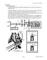
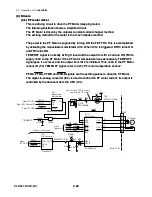
Reflective sensor (used for detecting the black mark on tag):
When tag with black marks is used, light is reflected by the tag. In the place where no
black mark is there, the phototransistor of the reflective sensor conducts and the voltage
corresponding to the amount of light is applied to pin 6 (ANI1) of IC1 (CPU). When the light
falls on the black mark, no light is reflected. In this case, the lower phototransistor turns
OFF and pin 6 of IC1 (CPU) will go “Low” level.
When media runs out, the light is not reflected and no light falls on the reflective sensor. In
this case, pin 6 of the CPU will go “Low” level and media end is detected.
As to the current control of the LEDs, the operation is the same as for the transparent
sensor.
+5V
Media
Transparent Sensor
[Main PCB]
Reflective Sensor
3
2
3
4
1
4
5
CN7
2
1
[Transparent Sensor PCB]
[Reflective Sensor PCB]
IC4
D/A Converter
CS
DIN
1
2
SCLK
3
7
DACCLK
DACCS
DACIN
TLV5625ID
Transparent sensor output sensing
terminal
OUTB
CN6
+3.3V
From
IC1 CPU
D8
R101
R102
TR4
2SA1037AKT146R
R100
C71
REFSENS
REFMON
TRANMON
ANI0
5
ANI1
6
IC1
CPU
+3.3V
LED current control
Reflective sensor output sensing
terminal
PESNSLED
DO NOT
ADJUST.
R112
R110
P211
R108
P214
TRASENS
IC14B
LMV932MM
-
+
VR1
5
6
7
R109
C97
P213
T15
R106
R111
VR2
P206
R104
P209
IC14A
LMV932MM
-
+
3
2
1
R105
C96
P208
T14
R98
R99
P41
LED
P202
T13
P217
P216
DO NOT
ADJUST.
P207
P212
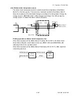
Caution:
y
DO NOT adjust VR1 and VR2 on the Main PCB. (Leave them at the factory setting
condition.) If it is changed, media sensor sensitivity is changed and the media
detection will not be correctly made.
Содержание CLP-621
Страница 1: ...Technical Manual CLP 621 CLP 631 Thermal Transfer Barcode Label Printer JM74961 00F 1 00E 0701...
Страница 2: ...CLP 621 CLP 631 ii Copyright 2007 by CITIZEN SYSTEMS JAPAN CO LTD...
Страница 4: ...CHAPTER 1 SPECIFICATIONS CLP 621 CLP 631...
Страница 13: ...CHAPTER 2 OPERATING PRINCIPLES CLP 621 CLP 631...
Страница 68: ...2 5 Power Supply CLP 621 CLP 631 2 56 N1 N2 N3 N4 BLOCK A BLOCK E BLOCK B BLOCK C BLOCK D 120V type...
Страница 69: ...2 5 Power Supply 2 57 CLP 621 CLP 631 N1 N2 N3 N4 Block A Block B Block C Block E Block D 220 240V type...
Страница 73: ...CHAPTER 3 DISASSEMBLY AND MAINTENANCE CLP 621 CLP 631...
Страница 126: ...CLP 621 CLP 631 CHAPTER 4 TROUBLESHOOTING...
Страница 138: ...CLP 621 CLP 631 CHAPTER 5 PARTS LISTS...
Страница 143: ...Chapter 5 Parts Lists CLP 621 CLP 631 5 6 DRAWING NO 1 General Assembly Rev 0 1 7 8 2 3 4 2 10 11 12 9 5 2 13 14 10...
Страница 163: ...Chapter 5 Parts Lists CLP 621 CLP 631 5 26 DRAWING NO 6 Sensor U Unit Rev 0 4 16 3 2 1 9 10 11 5 8 6 12 7 13 14 15...
Страница 166: ...Chapter 5 Parts Lists CLP 621 CLP 631 5 29 DRAWING NO 7 Control Panel Unit Rev 0 4 3 2 1 5...
Страница 174: ...Chapter 5 Parts Lists CLP 621 CLP 631 5 37 DRAWING NO 9 Ribbon Unit Fan SA2 Rev 0 1 2 4 3 5 6 3...
Страница 177: ...Chapter 5 Parts Lists CLP 621 CLP 631 5 40 DRAWING NO 10 Accessories Rev 0 3 2 4 1...
Страница 179: ...CHAPTER 6 CIRCUIT DIAGRAMS CLP 621 CLP 631...
Страница 208: ...APPENDICES CLP 621 CLP 631...
Страница 211: ...B Mounting Diagrams B Mounting Diagrams B Mounting Diagrams CLP 621 CLP 631 AP 4 AP 4 B 1 Main PCB Main PCB Parts side...
Страница 212: ...B Mounting Diagrams AP 5 CLP 621 CLP 631 Main PCB Solder side...
Страница 213: ...B Mounting Diagrams CLP 621 CLP 631 AP 6 AP 6 B 2 Power Supply PCB 120V 220V B 2 Power Supply PCB 120V 220V...
Страница 214: ...B Mounting Diagrams AP 7 CLP 621 CLP 631 B 3 Ribbon Main PCB Parts side Solder side...
Страница 217: ......


