


3-6. Adjustments
CLP-621 & CLP-631
3-42
CLP-621 & CLP-631
3-42
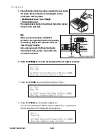
5. Peel off the label from liner (base) and set the liner part to
the printer. Be sure that the normal adjustments for
printing are correctly made.
• Media sensor menu: “See Through”
• Sensor positioning:
5. Peel off the label from liner (base) and set the liner part to
the printer. Be sure that the normal adjustments for
printing are correctly made.
• Media sensor menu: “See Through”
• Sensor positioning:
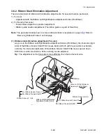
The upper sensor marker should meet the bottom sensor
marker on the right side.
The upper sensor marker should meet the bottom sensor
marker on the right side.
Tip:
Tip:
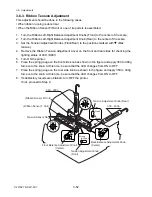
Guide, Paper Set
Aligned
When you move the upper and bottom
sensors to the right end (center of the printing
mechanism), they match with each other for
“See Through” position.
When you move the upper and bottom
sensors to the right end (center of the printing
mechanism), they match with each other for
“See Through” position.
Also, when you push the Paper Set Guide
toward them in any poison, they match with
each other as shown:
Also, when you push the Paper Set Guide
toward them in any poison, they match with
each other as shown:
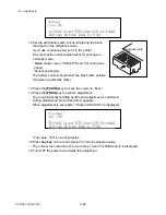
6. Press the
[FEED]
key to enter the transparent sensor adjustment mode.
6. Press the
[FEED]
key to enter the transparent sensor adjustment mode.
7. Press the
[PAUSE]
key to move the cursor to “Exec.”.
8. Press the
[FEED]
key to perform adjustment.
Liner is automatically fed little by little and adjustment is performed.
During adjustment, the following screen appears.
Содержание CLP-621
Страница 1: ...Technical Manual CLP 621 CLP 631 Thermal Transfer Barcode Label Printer JM74961 00F 1 00E 0701...
Страница 2: ...CLP 621 CLP 631 ii Copyright 2007 by CITIZEN SYSTEMS JAPAN CO LTD...
Страница 4: ...CHAPTER 1 SPECIFICATIONS CLP 621 CLP 631...
Страница 13: ...CHAPTER 2 OPERATING PRINCIPLES CLP 621 CLP 631...
Страница 68: ...2 5 Power Supply CLP 621 CLP 631 2 56 N1 N2 N3 N4 BLOCK A BLOCK E BLOCK B BLOCK C BLOCK D 120V type...
Страница 69: ...2 5 Power Supply 2 57 CLP 621 CLP 631 N1 N2 N3 N4 Block A Block B Block C Block E Block D 220 240V type...
Страница 73: ...CHAPTER 3 DISASSEMBLY AND MAINTENANCE CLP 621 CLP 631...
Страница 126: ...CLP 621 CLP 631 CHAPTER 4 TROUBLESHOOTING...
Страница 138: ...CLP 621 CLP 631 CHAPTER 5 PARTS LISTS...
Страница 143: ...Chapter 5 Parts Lists CLP 621 CLP 631 5 6 DRAWING NO 1 General Assembly Rev 0 1 7 8 2 3 4 2 10 11 12 9 5 2 13 14 10...
Страница 163: ...Chapter 5 Parts Lists CLP 621 CLP 631 5 26 DRAWING NO 6 Sensor U Unit Rev 0 4 16 3 2 1 9 10 11 5 8 6 12 7 13 14 15...
Страница 166: ...Chapter 5 Parts Lists CLP 621 CLP 631 5 29 DRAWING NO 7 Control Panel Unit Rev 0 4 3 2 1 5...
Страница 174: ...Chapter 5 Parts Lists CLP 621 CLP 631 5 37 DRAWING NO 9 Ribbon Unit Fan SA2 Rev 0 1 2 4 3 5 6 3...
Страница 177: ...Chapter 5 Parts Lists CLP 621 CLP 631 5 40 DRAWING NO 10 Accessories Rev 0 3 2 4 1...
Страница 179: ...CHAPTER 6 CIRCUIT DIAGRAMS CLP 621 CLP 631...
Страница 208: ...APPENDICES CLP 621 CLP 631...
Страница 211: ...B Mounting Diagrams B Mounting Diagrams B Mounting Diagrams CLP 621 CLP 631 AP 4 AP 4 B 1 Main PCB Main PCB Parts side...
Страница 212: ...B Mounting Diagrams AP 5 CLP 621 CLP 631 Main PCB Solder side...
Страница 213: ...B Mounting Diagrams CLP 621 CLP 631 AP 6 AP 6 B 2 Power Supply PCB 120V 220V B 2 Power Supply PCB 120V 220V...
Страница 214: ...B Mounting Diagrams AP 7 CLP 621 CLP 631 B 3 Ribbon Main PCB Parts side Solder side...
Страница 217: ......


